
NTSC RGB Cable Schematic
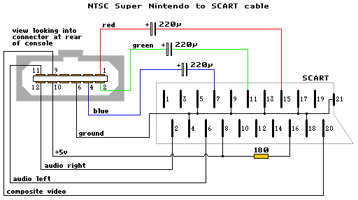
The schematic in question outlines the connections necessary for interfacing a Super Nintendo Entertainment System (SNES) with a display device via RGB output. The RGB lines facilitate a direct transmission of video signals, which are essential for achieving high-quality visuals. The inclusion of capacitors in the original SNES NTSC RGB cable design serves to filter and stabilize the signal, preventing interference and ensuring a clear image. However, in the modified version, these capacitors are omitted, which may lead to a more straightforward yet potentially less stable signal transmission.
When utilizing a GameCube SCART lead, it is crucial to remove the capacitors from the RGB lines to maintain compatibility with the SNES system. This step is vital as the capacitors can introduce unwanted attenuation or distortion to the signal, resulting in degraded image quality. The proposed method of twisting the capacitor legs together to create a bridge is a temporary fix that allows the circuit to function without the capacitors, although it may not be the most reliable long-term solution.
In the context of a GameCube PAL RGB cable, the differences in design between the PAL SNES and the GameCube cables must be considered. The GameCube's internal circuitry may incorporate capacitors that enhance signal integrity, which could contribute to a brighter picture when connected directly to the AV connector. However, if the RGB signal is routed directly from the encoder chip inputs, the absence of appropriate signal conditioning may lead to a dark picture, indicating that additional components or modifications may be necessary for optimal performance.
The concept of a "booster" refers to an amplification circuit that can enhance the signal strength of the RGB output, ensuring that the display receives a strong and clear image. This can be particularly important when interfacing with older display technologies that may not handle weak signals effectively. Understanding the role of such a booster can aid in troubleshooting and optimizing the RGB connection for both the SNES and GameCube systems.The diagram (schematic) is the same like the SNES NTSC RGB cable from here (only put capacitors to the RGB "line") or is different Yes the diagram is correct, but without the capacitors. You can use a Gamecube SCART lead but you must remove the capacitors on the RGB lines. A quick fix is to twist the legs of each capacitor together so that each connection is bridged respectively. What about a GameCube PAL RGB cable If you did straight from the encoder chip inputs to the AV connector, and used a PAL GC RGB cable would you still have a dark picture or a normal picture I seem to remember hearing that a PAL SNES and GC RGB cable are different because the GC has some caps or something inside the cable. So if I connected RGB to the connector would my GC RGB cable work with proper picture and not a dark one I guess it would help if I knew what this "booster" idea was.
What about a GameCube PAL RGB cable If you did straight from the encoder chip inputs to the AV connector, and used a PAL GC RGB cable would you still have a dark picture or a normal picture I seem to remember hearing that a PAL SNES and GC RGB cable are different because the GC has some caps or something inside the cable. So if I connected RGB to the connector would my GC RGB cable work with proper picture and not a dark one I guess it would help if I knew what this "booster" idea was.
🔗 External reference
Related Circuits
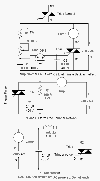
Advanced power control systems utilize electronic components such as thyristors for power switching, motor control, and other applications. These systems are involved in inverter design, lamp dimming, and speed control of motors. Triacs are the most commonly used semiconductor...
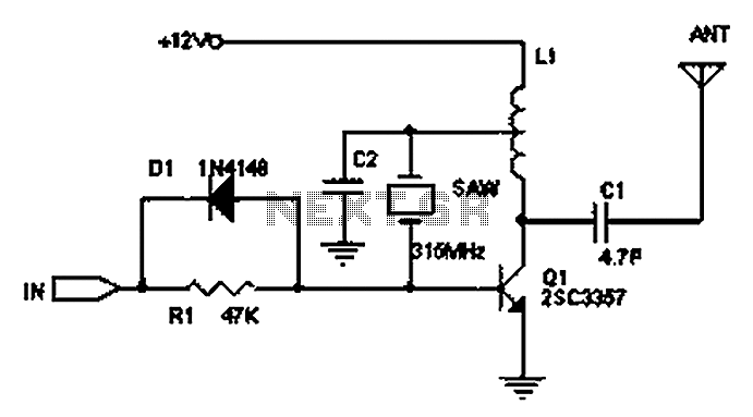
The circuit principle involves the use of an LC oscillator, which typically experiences significant frequency drift. Surface Acoustic Wave (SAW) devices have emerged as a solution to this issue, offering frequency stability comparable to that of crystal oscillators. SAW...
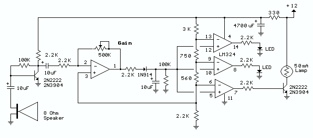
The circuit below responds to sound pressure levels from about 60 to 70 dB. The sound is picked up by an 8 ohm speaker, amplified by a transistor stage and one LM324 op-amp section. You can also use a...
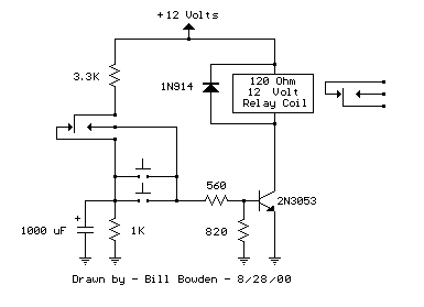
The circuit below requires a double pole, double throw relay in conjunction with a single transistor to allow toggling the relay with a momentary push button. One set of relay contacts is used to control the load, while the...
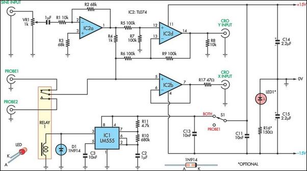
This unit utilizes a dual trace oscilloscope with X-Y functionality as a display to test and demonstrate the operation of circuits and components such as transistors, diodes, zener diodes, and both terminated and unterminated transformers. A low-frequency sine wave...
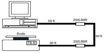
This is the schematic diagram of a 9-Pin RS232 Line Booster Signal Direction. The device functions as a 9-pin RS-232 repeater, re-transmitting all 8 signals while also maintaining the ground line. The 9-Pin RS232 Line Booster is designed to extend...