
RGB LED Strip Circuit with Arduino

The circuit assembly for PWM control of a high-power RGB LED strip involves several key components and considerations to ensure proper functionality and safety. The primary components include an Arduino microcontroller, a transistor (such as a TIP120), a 7805 voltage regulator, and the RGB LED strip itself. The Arduino is used to generate PWM signals that control the brightness of the RGB LEDs by varying the duty cycle of the output signal.
The transistor acts as a switch, allowing the Arduino to control a higher current load from an external power source, which is necessary since the Arduino's output pins can only handle a maximum of 40mA. The transistor should be mounted on a heatsink to dissipate heat generated during operation, particularly when handling high currents. Thermal compound should be applied between the transistor and heatsink to enhance thermal conductivity.
The RGB LED strip consists of multiple LEDs arranged in a series configuration. Each LED typically requires 3.3V and can draw up to 60mA when all color channels are active. To power the strip effectively, an external power supply within the 9-12V range is necessary, and the total voltage required for a strip of three LEDs in series should be calculated to ensure compatibility with the power source.
Proper wiring techniques are crucial for circuit assembly. Color-coded wires can help prevent mistakes, and the use of heat shrink tubing can protect connections from shorts. The schematic for the circuit should be carefully followed, ensuring that all connections are made to the correct pins as indicated in the datasheets for each component.
When programming the Arduino, it is essential to understand the limitations of the microcontroller in terms of PWM outputs, especially when working with smaller chips like the ATTiny85. The programming environment allows for flexibility, and users are encouraged to explore existing libraries and examples to facilitate the development of their projects.
Overall, this circuit design provides a robust platform for controlling RGB LED strips with an Arduino, allowing users to create a dynamic lighting experience through programming and hardware integration.This Instructable covers the assembly of a circuit capable of PWM-ing ( pulse width modulating ) a high-power RGB LED strip and programming an Arduino to cycle through a range of colors. In this context, high power is 9-12 volts. I will discuss how to mount a transistor to a heatsink and assemble the circuit. I will not go into soldering as som e of the RGB LED strip comes with leads (and there is no shortage of great tutorials out there). Also, I will use the most plain, non-jargony language possible to explain the circuit because I know how frustrating it can be to learn this stuff. Note 1: I am in no way affiliated with any of the companies mentioned or linked to, including Arduino, Jameco, Adafruit, and Sparkfun.
I receive no compensation for the publication of this Instructable by any of the aforementioned companies. If you are new to Arduino and are wondering why more than a few LEDs or other components like motors won`t activate when functions are called in the code, its because each output has a current limit of 40mA.
In other words, a component cannot draw more than 40mA of current from each channel. To refer to the water analogy of electronics, the pump pressure is 5V, and the amount of water is the number of electrons (measured in Amps, or in our case, a much smaller amount milliamps, mA). To accommodate a load that requires more current than 40mA at 5V, we will use our microcontroller to control a transistor, which will provide a component with power from an external source (the battery).
Without getting too technical, its worth knowing that individual strips are made up of 3 LEDs in series which can be cut with clippers at any junction. If you want to cut the strip at any point, just be sure to leave connection points on each halve. To understand how the RGB LED strip can be powered with 9-12V, you need to know the difference between circuits in series vs.
parallel (this page has a simple explanation with great illustrations, and there is a popular Instructable that covers wiring LEDs in series & parallel ). Basically, when LED`s are connected in series, the supply voltages and necessary current are added together (respectively).
For example, since an average RGB LED requires 3. 3 V and 60mA (at full brightness; each color channel draws 20mA, so R-G-B all on at same time is 20 x 3 = 60mA), each strip of 3 RGB LEDs will require approximately 9. 9V ( the strip I`m using from Jameco can be powered between 9-12V. Be sure to look at your product`s datasheet to prevent frying your components. Not all RGB LED strip is powered in the 9-12V range, such as Adafruit`s digitally addressable RGB LED strip ).
One more thing, these strips are common anode, meaning the LEDs share a positive terminal ( read about anode vs. cathode ). Perhaps the greatest take-away is the power limitation of the Arduino. The next section which shows how to use a transistor can be applied to all sorts of other components (ex.
motors, solenoids, servos) that require more than 40mA at 5V. Note: Since I mentioned digitally-addressable strips, its important to recognize a limitation of the strip I`m using all of the LEDs will behave in the exact same way as you will see. Digitally-addressable RGB LEDs are pretty awesome in that each LED can be accessed individually (check out this cheesy/awesome video ) A heat sink s function is to dissipate heat so components don`t fry, melt connections/become un-soldered, or become too hot to touch.
This is really important if you`re using a 7805 for voltage regulation, which I`m also doing in this circuit. The 7805 will output a steady 5V to the microcontroller and dissipate quite a bit of heat. I like to do this because I don`t trust the Arduino SMD voltage regulator, especially on ProMinis which I use frequently (even thought the Arduino Uno datasheet says the input voltage can be as high as 20V).
This part is pretty straight-forward. Apply some heat sink compound to the transistor (first image in this series) and then put the nylon washer on screw on then through the transistor (second). The compound increases thermal conductivity, which aids in the dissipation process. Lastly, fasten the nut to the back of the heat sink. Now that the transistors and 7805 are mounted to heat sinks, let`s assemble the circuit. I think its worth noting that you`ll save yourself time and frustration if you use good breadboarding techniques such as color-coding wire connections, and using heat shrink tubing to prevent shorts (see image of battery).
Its considerably easier to find errors too when your wire connections are shorter and color-coated. I think the only way to learn this is the hard way, but I figured its worth mentioning. The first schematic is for an Arduino full-development board (Uno, Pro Mini, etc), but is essentially the same if you want to use an ATTiny (for this component, you just need to hook it up to the right pins ). If you are breadboarding the circuit, be sure to look up the datasheets and pinouts for your exact components.
I have provided a simple illustration depicting the pinouts for the components I`m using (Tip 120, 7805). If you are unfamiliar with reading schematics, here is a pretty good tutorial and a symbol guide. Important Note: You can fry your Arduino if it is powered by the battery via V-in and the USB cable at the same time.
Unplug the battery before you upload programs. Also, if you want to power your Arduino via USB during development and still leave battery plugged in (to power the strip), simply remove the connection between the output of 7805 to V-in, but be sure that you still have ground connected, otherwise it won`t work. The deeper I get into Arduino, the more I find myself programming chips directly using an ISP (In-System Programmer, I use Jeff Murchison`s ISP shield but there are cheaper ways of doing this such as using the Arduino directly ), and learning AVR proramming.
I bring this up because there seems to be a bit of confusion out there regarding the ATTiny85 as to whether it has two or more PWM outputs. The answer seems to be that if you write your program using the Arduino language, you`ll only be able to access two, but interfacing with the hardware directly in C (still written in the Arduino IDE) can allow for more.
This is beyond the scope of this tutorial, but here is a good starting point that really helped me learn it. So now that you have a functional circuit, its time to upload some code. If this is your first Arduino program, it may be helpful to example a digitalWrite blinking program before moving on to fading in order to understand the structure of the language.
Its taken me quite a while to realize that there`s no reason to reinvent the wheel, and with the current obsession with all things blinky, I`ve also realized that there`s no reason for me to write a program to demonstrate the range of colors for an RGB LED. Clay Shirky has published a pretty convenient program, which is a good starting point for controlling your RBG LED strip before making it interactive with some kind of input.
Have fun! 🔗 External reference
Related Circuits
The circuit receives its input from the zero-crossing detector, which generates a 0-to-1-to-0 pulse to set the R-S flip-flop and activate the ramp circuit (A to Ramp) to initiate the timing ramp ascent. The described circuit operates by utilizing a...

The automotive LED driver circuit diagram utilizes the LT3486. The LED is employed in the car's central high-mounted stop lamp (CHMSL), providing advantages such as faster achievement of the set brightness, higher efficiency, longer lifespan, and simplified design and...

The circuit depicted in Figure 5-60 and Figure 6 utilizes an operational amplifier (op-amp) configured as a channel pre-amplifier to address the signal loss introduced by the tone control circuit. Additionally, another group of op-amps forms a channel-driven stage...
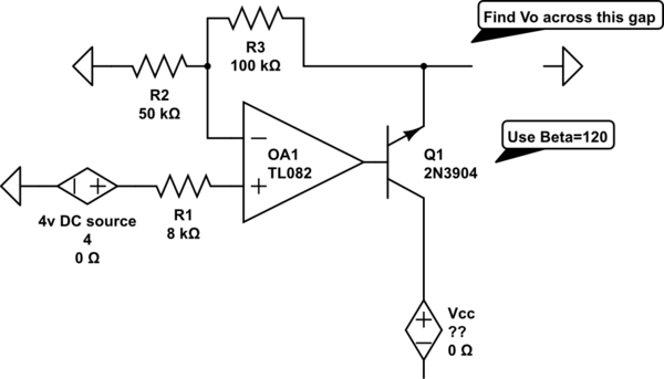
The voltage measured at 12V after the emitter is perplexing, especially when the output from the op-amp is +15V, suggesting a 3V drop across the transistor. This raises questions about the expected gain of 2, which would imply an...

In the 555 oscillator circuit, adjusting R2 will provide output frequencies ranging from below 200 Hz to above 62 kHz. It is recommended to use a good quality miniature speaker to produce frequencies around 20 kHz. The 555 oscillator circuit...

The inverting input is maintained at a low level via a 10K resistor when the circuit is powered on but not in use. During measurement activities, including calibration measurements where the input is floating, this resistor is disconnected. The...