
SG3525A Pulse Width Modulator Control Circuits

The Audison LR604XR amplifier utilizes a straightforward yet effective design principle that integrates a DC-DC converter and analog circuitry. The SG3525A pulse width modulator serves as the heart of the control mechanism, enabling improved performance and a reduced count of external components. This modulator is particularly beneficial for various switching power supply applications due to its efficiency and reliability.
In the schematic, the SG3525A is configured to provide a regulated output voltage, leveraging its on-chip +5.1 V reference, which is precisely trimmed to ensure minimal deviation. The error amplifier within the SG3525A monitors the output voltage, adjusting the duty cycle of the PWM signal to maintain the desired output level.
The push-pull converter topology employed in this design allows for effective voltage conversion, utilizing a transformer with dual primary windings. This configuration enables the efficient transfer of energy, minimizing losses and maximizing output power. The center tap connection ensures that the circuit can effectively manage the alternating current flow necessary for the push-pull operation.
Furthermore, the PWM control of DC motors using this configuration allows for accurate speed regulation. The circuit converts the DC voltage into a series of pulses, where the duration of each pulse correlates directly with the input voltage. This method provides a high level of control over the motor's speed and torque, making it suitable for applications requiring precise motor management.
Overall, the combination of the SG3525A modulator and the push-pull converter topology in the Audison LR604XR amplifier design exemplifies a robust solution for audio amplification and motor control, showcasing efficiency, precision, and adaptability in various electronic applications.This article describes an amplifier Audison LR604XR principle. The principle is simple there, we recommend that combine text carefully read the complete schematic. To better grasp this principle, it is recommended to read several times on this principle. 1. Layout DCDC converter and analog par. The SG3525A pulse width modulator control circuits off er improved performance and lower external parts count when implemented for controlling all types of switching power supplies. The on–chip +5. 1 V reference is trimmed to ±1% and the error amplifier has an input common&nda. SG3525 DC Converter 12V to +35V, -35V SG3525 DC Converter 12V to +35V, -35V The selected switching topology is called a "push-pull" converter, because the transformer has a double primary (or a "center-tapped" one, if your prefer).
The center tap is permanently connected to the c. PWM DC motor using SG3525Circuit diagram is one of a series of PWM. Circuit diagram is ideal for accurate control of DC motors. DC voltage conversion to a series of pulses, such that the duration of the pulse is a direct proportion to the value of DC voltage. Big advantage as the circuit is that alm. Circuit diagram is one of a series of PWM. Circuit diagram is ideal for accurate control of DC motors. conversion of DC voltage pulses to the circuit IC is controlled by SG3525, such that the pulse duration is directly proportion to the value of DC voltage.
Big advantage as the circuit is that alm. 🔗 External reference
Related Circuits
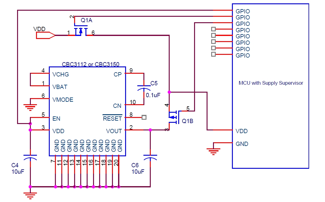
Cymbet Corporation provides rechargeable solid-state batteries designed for advanced microcontroller power backup applications. The company is recognized as a leader in thin-film energy storage technology. Cymbet Corporation's rechargeable solid-state batteries are engineered to deliver reliable power solutions for microcontrollers, which...
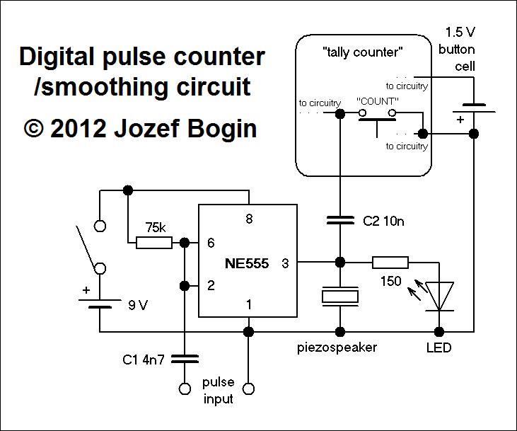
This is a simple yet versatile pulse counting and smoothing integrator circuit featuring an NE555 timer as the waveform shaper and a small LCD display for output. Originally designed for counting pulses from Geiger counters, it includes a piezo...
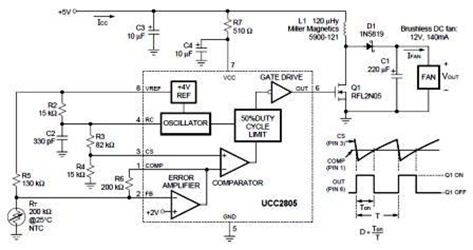
A temperature-controlled pulse-width-modulator (PWM) boost converter circuit diagram is illustrated in the following figure. This boost converter is designed to operate a 12V fan using a 5V supply while maintaining temperature control. The temperature-controlled PWM boost converter circuit operates by...
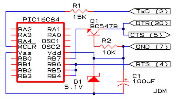
Affordable PIC Programmer. This programmer is compatible solely with the PIC16F84 microcontroller. It is reliable, as it rarely encounters errors, and functions well with nearly all computer systems, in contrast to some alternatives. The PIC programmer designed for the PIC16F84...
The circuit utilizes standard components, produces a good sine wave, and exhibits a degree of immunity to the specific operational amplifier it is designed around. However, it can be easily misunderstood, and oversimplifications regarding its operation may lead designers...
This design is based on a publication by Milan Lulic in the German magazine elektroModell. Lulic's design utilizes surface mount technology (SMT), while this version employs standard off-the-shelf components, making it more accessible for hobbyists. For those interested in...