


Simple Cat.5 Network Tester
#network tester
#Cat.5
#LED
#continuity test
#one-person operation
#quick test
#dirty test
#remote check
#transmitter
#cycling test
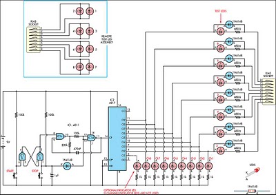
Description: This circuit was developed to create a simple network tester that can be operated by a single individual. Commercial units typically require a second person to monitor the remote LEDs, as the transmitters lack the ability to continuously cycle through tests, making it difficult for one person to assess both ends. It is important to note that this unit is designed solely to check for pair continuity, pair shorts, crossed wires, and shorts to other pairs. It does not test bandwidth or other parameters. The operation of the device is relatively straightforward. One half of the 4011 quad 2-input NAND gate functions as an RS flip-flop (IC1a, IC1b), which controls the other half, IC1c and IC1d, that operates as a clock oscillator. The oscillator can be started and stopped using the Start and Stop switches or, via diode D1 connected to pins 12 and 13, the Stop switch can be used for manual clocking of the 4017 counter. The 4017 drives one of eight LEDs and the connections to the RJ45 socket. A High output on the 4017 determines which line is being tested; if the circuit is complete, the test LED's current is sunk by the 4017, causing the LED to illuminate. If the corresponding test LED on the remote end does not light, it indicates a short in that pair of the cable under test. If multiple LEDs light up, it signifies a short with another pair. A non-illuminated test LED on the transmitter indicates that the pair is an open circuit. The Start function initiates the circuit cycling at a rate determined by the 470nF capacitor and 220kΩ resistor, while the Stop/Step function halts cycling, allows stepping through the lines, and effectively switches the unit off when no channel LEDs are lit, resulting in a standby drain current of less than a microamp.
This network testing circuit employs a 4011 quad 2-input NAND gate to facilitate its operations. The RS flip-flop configuration (IC1a and IC1b) allows for the storage of a binary state, which is essential for controlling the clock oscillator (IC1c and IC1d). The oscillator generates a square wave signal, which is critical for sequentially activating the 4017 decade counter. The 4017 counter is responsible for sequentially lighting one of the eight LEDs corresponding to the RJ45 socket connections.
The Start switch initiates the operation, allowing the oscillator to run continuously, while the Stop switch pauses the operation, providing a manual stepping feature through the lines. The presence of diode D1 enables the manual clocking feature, which is useful for troubleshooting and verifying individual connections without continuous cycling.
The circuit is designed with user-friendliness in mind, allowing one person to perform network tests efficiently. When a test LED lights up, it confirms the integrity of the cable connection; conversely, when the LED does not illuminate, it indicates an open circuit. The ability to detect shorts between pairs enhances the diagnostic capability of the device. The standby current consumption of less than a microamp ensures that the circuit is energy-efficient, making it suitable for prolonged use without significant battery drain.
Overall, this network tester is a practical solution for assessing network cabling integrity, providing essential feedback through visual indicators while maintaining simplicity in operation.This circuit came from a need for a quick and dirty network tester that could be operated by one person. All the commercial units I tried required a person at the other end to check the remote LEDs, as the transmitters could not be made to cycle through the test continuously to allow one person to check both ends.
It must be noted that this uni t will only check for pair continuity, pair shorts, crossed wires, and shorts to other pairs. It will not test bandwidth, etc. Operation is fairly basic. Half of the 4011 quad 2-input NAND gate is an RS flip-flop (IC1a, IC1b) which controls the other half, IC1c & IC1d, operating as a clock oscillator. You can either start and stop the oscillator running by pressing the Start and Stop switches or by virtue of diode D1 connected to pins 12 & 13, use the Stop switch to allow manual clocking of the 4017 counter.
The 4017 drives one of eight LEDs and the lines to the RJ45 socket. An output High on the 4017 decides which line is under test, and if the circuit is complete, the test LED`s current is sunk by the 4017 and the LED will light. If the corresponding test LED on the remote fails to light, then there is a short of that pair in the cable under test.
If more than one LED lights, it indicates a short with another pair. A dark test LED on the transmitter indicates that pair is open circuit. Start starts the circuit cycling at a rate determined by the 470nF capacitor and 220kO resistor and Stop/Step stops cycling, steps through the lines, and when stepped so that no channel LEDs are alight, effectively switches the unit off with a standby drain current of less than a microamp.
This network testing circuit employs a 4011 quad 2-input NAND gate to facilitate its operations. The RS flip-flop configuration (IC1a and IC1b) allows for the storage of a binary state, which is essential for controlling the clock oscillator (IC1c and IC1d). The oscillator generates a square wave signal, which is critical for sequentially activating the 4017 decade counter. The 4017 counter is responsible for sequentially lighting one of the eight LEDs corresponding to the RJ45 socket connections.
The Start switch initiates the operation, allowing the oscillator to run continuously, while the Stop switch pauses the operation, providing a manual stepping feature through the lines. The presence of diode D1 enables the manual clocking feature, which is useful for troubleshooting and verifying individual connections without continuous cycling.
The circuit is designed with user-friendliness in mind, allowing one person to perform network tests efficiently. When a test LED lights up, it confirms the integrity of the cable connection; conversely, when the LED does not illuminate, it indicates an open circuit. The ability to detect shorts between pairs enhances the diagnostic capability of the device. The standby current consumption of less than a microamp ensures that the circuit is energy-efficient, making it suitable for prolonged use without significant battery drain.
Overall, this network tester is a practical solution for assessing network cabling integrity, providing essential feedback through visual indicators while maintaining simplicity in operation.This circuit came from a need for a quick and dirty network tester that could be operated by one person. All the commercial units I tried required a person at the other end to check the remote LEDs, as the transmitters could not be made to cycle through the test continuously to allow one person to check both ends.
It must be noted that this uni t will only check for pair continuity, pair shorts, crossed wires, and shorts to other pairs. It will not test bandwidth, etc. Operation is fairly basic. Half of the 4011 quad 2-input NAND gate is an RS flip-flop (IC1a, IC1b) which controls the other half, IC1c & IC1d, operating as a clock oscillator. You can either start and stop the oscillator running by pressing the Start and Stop switches or by virtue of diode D1 connected to pins 12 & 13, use the Stop switch to allow manual clocking of the 4017 counter.
The 4017 drives one of eight LEDs and the lines to the RJ45 socket. An output High on the 4017 decides which line is under test, and if the circuit is complete, the test LED`s current is sunk by the 4017 and the LED will light. If the corresponding test LED on the remote fails to light, then there is a short of that pair in the cable under test.
If more than one LED lights, it indicates a short with another pair. A dark test LED on the transmitter indicates that pair is open circuit. Start starts the circuit cycling at a rate determined by the 470nF capacitor and 220kO resistor and Stop/Step stops cycling, steps through the lines, and when stepped so that no channel LEDs are alight, effectively switches the unit off with a standby drain current of less than a microamp.
Electronics/Transmitter design
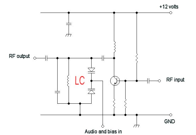
For a fixed frequency transmitter, a common method is to use a resonant quartz crystal in a crystal oscillator to establish the frequency. In transmitters where the frequency must be variable, several options are available. It is often the case...
Light Related
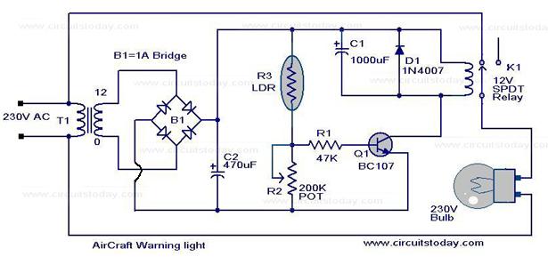
Watch the video below to gain a better understanding of how a light-emitting diode (LED) functions. An LED is recognized as one of the most effective optoelectronic devices available. This device emits a relatively narrow bandwidth of visible or invisible...
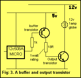
508A microcontroller can deliver a maximum of 25mA
A typical device that requires less than 5v and draws less than 25mA is an LED. A LED must be supplied with an exact voltage for it to operate correctly. Because it requires LESS than 5v, a dropper resistor (current...
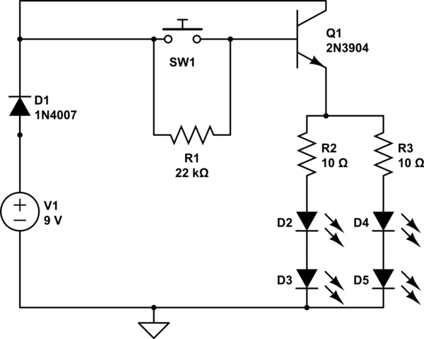
Switching intensity of LEDs
A circuit has been constructed that functions unexpectedly. The circuit utilizes red 5mm LEDs as diodes, a 3904 NPN transistor, and resistors as indicated in the schematic. Logically, pressing the push button normally open (PBNO) should result in the destruction...
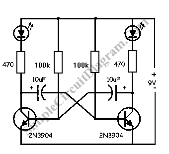
LED Flasher Using Transistor
This simple LED flasher circuit will alternately turn ON and OFF two LEDs. The first LED will illuminate when the second LED is OFF for a certain duration, and then the process will repeat.
The LED flasher circuit operates using a...
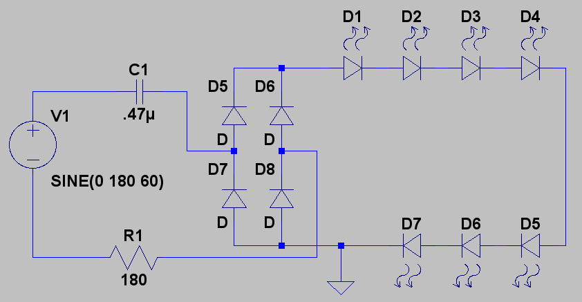
cf led lamp
Create LED lighting powered directly from the AC mains (120-Volt AC) due to the unavailability of inexpensive and safe enclosures for the circuitry. While collecting old failed CFLs for recycling, it was noted that the body of CFLs (also known...
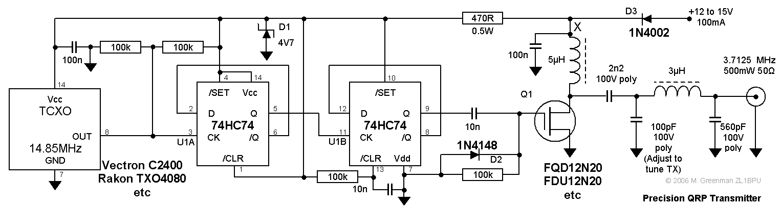
Precision QRP Transmitter
This compact transmitter is suitable for less demanding Doppler propagation measurements. It is designed for operation on the 80m band but can be easily adapted for the 40m or 20m bands. The output power is approximately 500mW of unmodulated carrier,...

Deluxe Crystal Controlled Transmitter
A high-quality QRP transmitter, named NEXUS 6, is designed to explore issues related to extremely narrow bandwidth communication. This device is not merely a simplified version of a QRP transmitter; it aims to create a cost-effective system that can be...
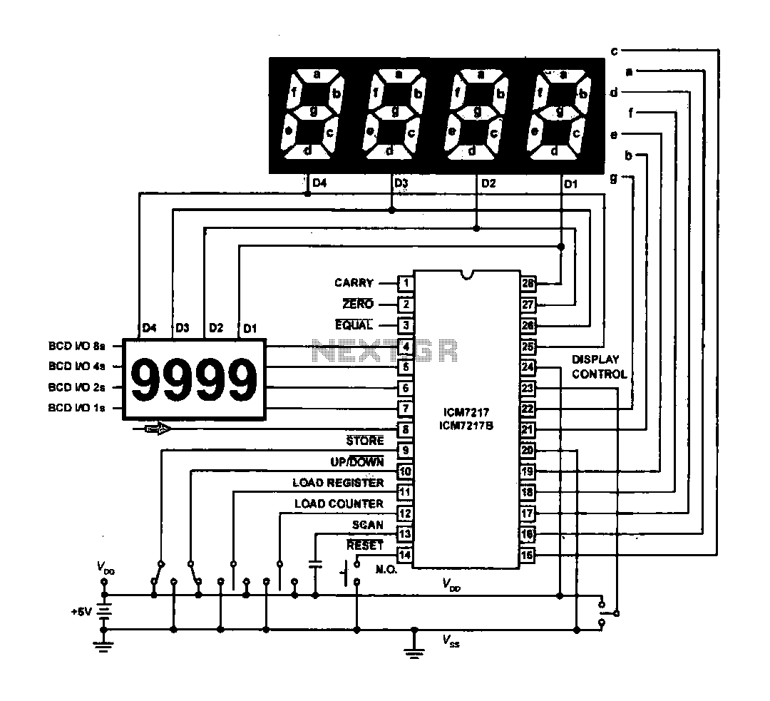
Light emitting diode LED displays the basic structure of the driving circuit
The circuit drives the light-emitting diode in a digital display configuration. The count signal is fed into the ICM7217 chip, which processes the count and subsequently drives the digital display board. The connection between the thumbwheel switches is illustrated in...