
Solar Tracker
The solar tracker circuit is designed to optimize the positioning of solar panels to maximize exposure to sunlight throughout the day. It typically employs a dual-axis tracking system, which allows the panels to move both horizontally and vertically, following the sun's path. The core components of such a circuit usually include light-dependent resistors (LDRs) for detecting sunlight intensity, a microcontroller for processing the input signals, and motor drivers to control the movement of the solar panels.
The LDRs are strategically placed on the solar panel to sense the light intensity from different directions. When one side receives more light than the other, the microcontroller interprets this data and sends signals to the motor drivers, which activate the motors to adjust the panel's angle accordingly. This process ensures that the solar panels are always oriented towards the sun, thereby enhancing energy capture efficiency.
Additionally, the circuit may feature a power supply section that includes a battery management system to store excess energy generated during peak sunlight hours. This stored energy can be used to power the tracker during periods of low sunlight or at night.
For users looking to customize the circuit, the open-source nature allows for modifications in the code running on the microcontroller, enabling the implementation of additional features such as weather sensors or remote monitoring capabilities. The accompanying video provides insights into these features and demonstrates how to make the necessary adjustments for specific requirements. Overall, the solar tracker circuit represents a valuable tool for improving solar energy harnessing capabilities.This solar tracker circuit is an open source circuit and anyone may edit the circuit to his/her own preference. Watch the video for other useful information regarding features the solar tracker does and does not include that you may have to implement yourself.
🔗 External reference
Related Circuits
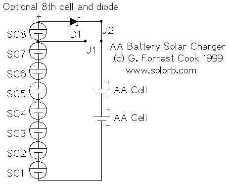
This almost trivial circuit may be used to charge a pair of AA or AAA sized rechargeable battery cells from sunlight. The circuit has been used to keep a Palm Pilot and walkman radio running perpetually. This is an...
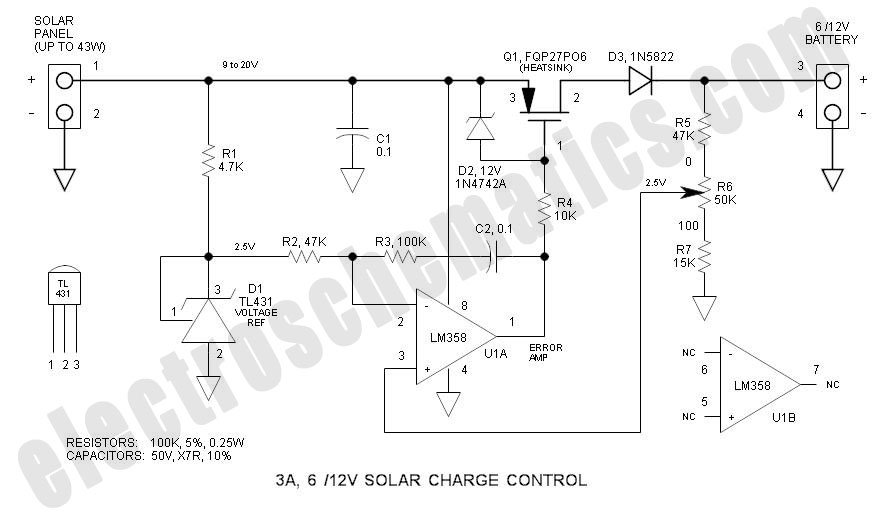
This solar charge controller integrates multiple features into a single design, including a 3A current rating, low dropout voltage (LDO), and a range of voltage adjustment capabilities. The solar charge controller is a critical component in solar energy systems, tasked...
It is possible to reduce electricity bills by utilizing alternative power sources. The photovoltaic module, or solar panel, described here, can produce a power output of 5 watts. Under full sunlight conditions, the solar panel generates 16.5V and can...
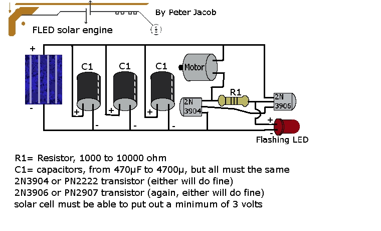
This document outlines the construction of a trimet. The required components include three capacitors, a 2N3904 transistor, a 2N3906 transistor, a resistor with a value between 1k to 10k ohms, and a solar cell with a minimum voltage of...

Sustainable satellite 802.11b wireless internetwork and how it was achieved. The design of a sustainable satellite 802.11b wireless internetwork involves the integration of satellite communication technology with wireless networking standards to create a robust and efficient communication system. This architecture...
The calibration circuit operates in inject mode, generating a square wave output in the audio range, where power harmonics can be detected at several Hertz. In tracking mode, the amplifier detects non-linear operation by filtering a modulated RF signal...