
Transistor and diode tester
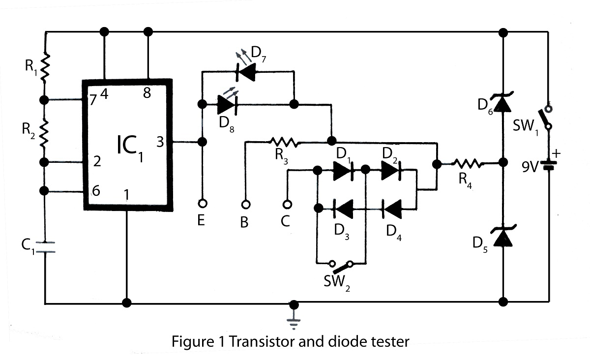
The transistor and diode tester is an essential tool for electronics engineers and hobbyists, allowing for the evaluation of semiconductor devices' functionality. This device typically incorporates a microcontroller or an integrated circuit that enables users to perform tests on bipolar junction transistors (BJTs), field-effect transistors (FETs), and diodes.
The testing process generally involves applying a small voltage to the device under test (DUT) and measuring the resulting current flow. For transistors, the tester can determine parameters such as current gain (hFE), threshold voltage, and the type of transistor (NPN or PNP). For diodes, it checks forward and reverse bias characteristics, ensuring that the diode conducts in one direction while blocking in the other.
The schematic of such a tester would typically include a power supply circuit, a microcontroller for processing the test results, and input/output interfaces for connecting the DUT. The power supply could be derived from a battery or an external source, providing the necessary voltage levels for testing. The microcontroller would interface with analog-to-digital converters (ADCs) to measure current and voltage levels accurately.
Additionally, the testing circuit may include a series of resistors to limit current flow, as well as indicators such as LEDs to provide visual feedback on the test results. The user interface might consist of buttons for selecting test modes and a display for showing the results, which could be implemented using an LCD or OLED screen.
Overall, this transistor and diode tester not only simplifies the process of testing semiconductor devices but also enhances reliability and efficiency in electronic troubleshooting and development tasks.Transistor and diode tester in this website is specially design for testing all kind of transistor .using diode principle diode can also be checked.various type of testing circuit you found here . 🔗 External reference
Related Circuits
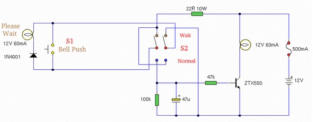
This article outlines various audiophile projects, including the DDDAC 2000, and discusses components such as the 1N4001 diode. The content is straightforward and informative, providing insights into these projects. For instance, readers can find and purchase the 1N4001 diode...
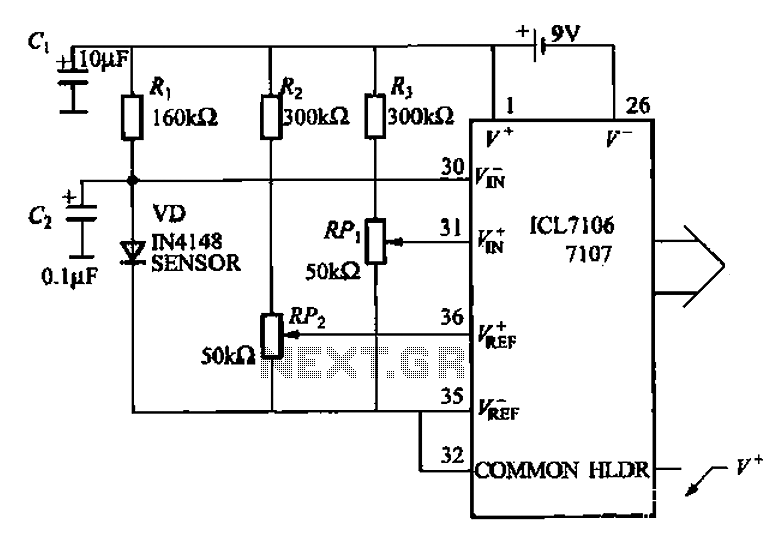
A diode temperature sensor is utilized in a 3-digit thermometer, featuring a 3-digit A/D converter and display driver IC L7106/7107. This configuration amplifies the signal, performs A/D conversion, and executes a series of decoding and display driver processes to...
The speed of light has been measured using various ingenious methods. This note describes a conceptually simple and relatively easy-to-implement technique known as the time-of-flight optical pulse delay method. It utilizes a short (nanosecond) optical pulse and an oscilloscope...
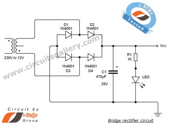
A rectifier is an electronic circuit that converts AC voltage to DC voltage. It can be implemented using a combination of capacitors and diodes. The unique property of diodes, which allows current to flow in a single direction, is...
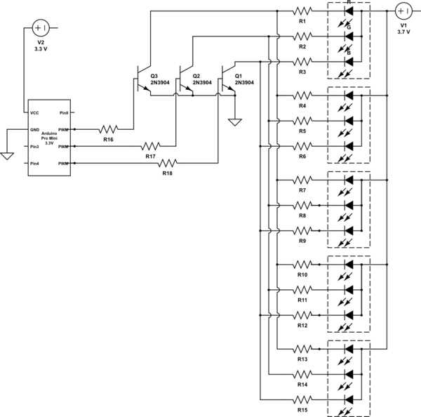
It is noted that the LEDs are not configured in parallel with the transistor. If they were, the LEDs would illuminate when the transistor is off. Instead, the LEDs are connected in parallel before entering the transistor. The transistor...
These frequencies include TV in VHF and UHF, as well as the radio broadcasting frequencies in the 88 - 108 MHz FM band. Component: Resistor, IC. The circuit described operates within the VHF (Very High Frequency) and UHF (Ultra High...