
arduino LCD
To connect an LCD display to an Arduino, first gather the necessary components: an Arduino board (such as the Arduino Uno), a 16x2 LCD display, a breadboard, jumper wires, and a potentiometer (optional for contrast adjustment).
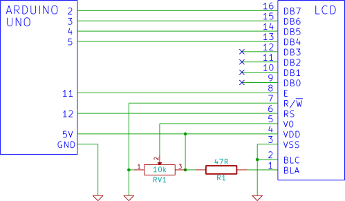
Begin by placing the LCD display on the breadboard. The typical 16x2 LCD has 16 pins, with the following relevant connections:
1. **Pin 1 (VSS)**: Connect to the ground (GND) of the Arduino.
2. **Pin 2 (VDD)**: Connect to the 5V power supply from the Arduino.
3. **Pin 3 (VO)**: Connect to the middle pin of a potentiometer (if used for contrast adjustment), with the other two pins connected to 5V and GND respectively. If a potentiometer is not used, this pin can be connected directly to ground for minimal contrast.
4. **Pin 4 (RS)**: This pin is for the register select. Connect it to a digital pin on the Arduino, commonly pin 12.
5. **Pin 5 (RW)**: Connect this pin to ground to set the LCD in write mode.
6. **Pin 6 (E)**: This is the enable pin. Connect it to another digital pin on the Arduino, typically pin 11.
7. **Pins 7-14 (D0-D7)**: These are the data pins. For a 4-bit mode, connect pins D4-D7 (pins 12-15) to digital pins on the Arduino (for example, pins 5, 4, 3, and 2).
8. **Pin 15 (LED+)**: Connect to 5V for the backlight.
9. **Pin 16 (LED-)**: Connect to ground.
After establishing the connections, upload a simple test sketch to the Arduino to initialize the LCD and display a message. The `LiquidCrystal` library is commonly used for this purpose. The code will set up the LCD dimensions, specify the pins used, and include commands to print text to the display.
Once the code is uploaded, power the Arduino, and the LCD should display the specified message, confirming that the connection is successful. This procedure provides a foundational understanding of interfacing an LCD with an Arduino, which can be expanded upon with more complex functionalities in future projects.How to connect a LCD display to an Arduino and test it. This tutorial shows beginners how to use a breadboard to connect an LCD display to an Arduno, step by step.. 🔗 External reference
Related Circuits
Many educational haptic feedback devices utilize kinesthetic force feedback systems like the Novint Falcon and the Phantom Omni. While these devices are relatively affordable compared to higher-end haptic systems, they remain costly for educational purposes. Consequently, a team has...
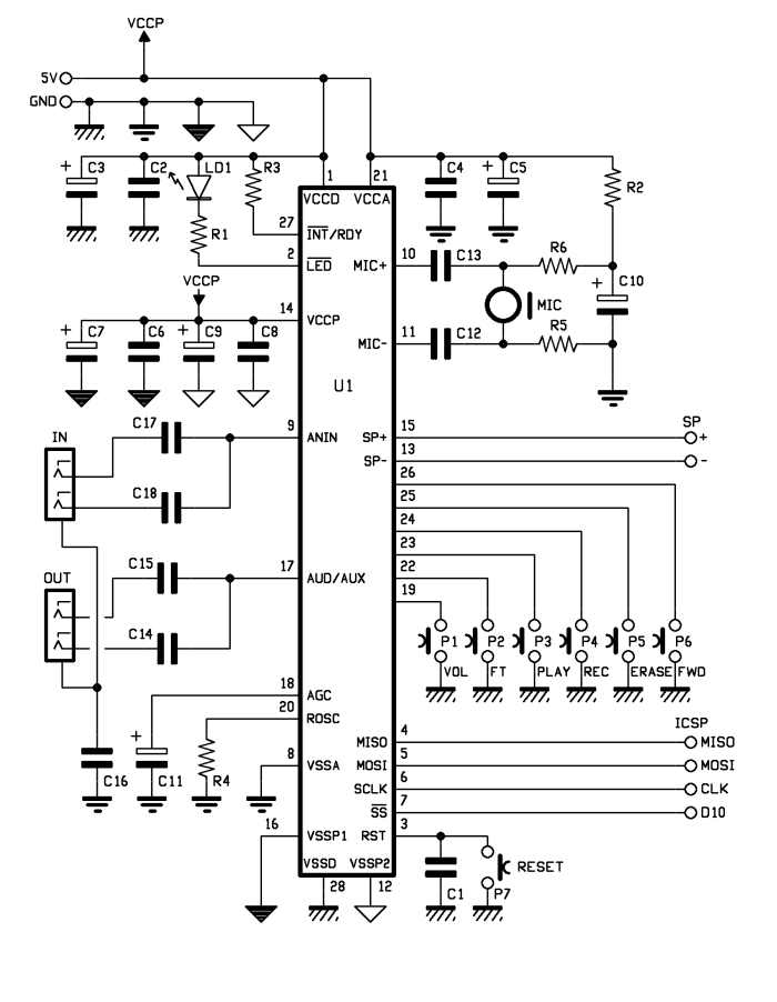
The aim of this project is to create an Arduino voice shield that facilitates numerous voice-related applications, primarily utilizing an integrated ISD1790PY chip. This voice and text-to-speech (TTS) functionality can be beneficial for integrating voice messages into alarm systems,...
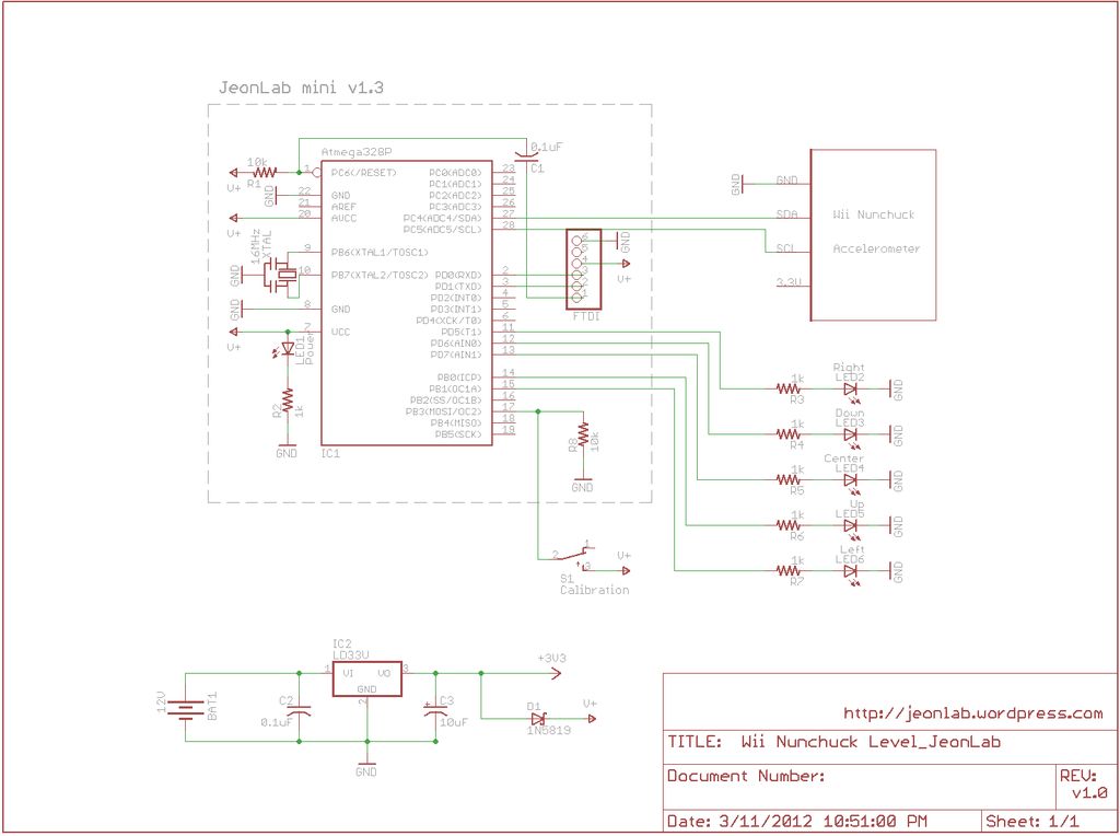
After reading an article on the Todbot blog, a purchase was made for several Wii Nunchucks from eBay. The exact amount paid is not recalled, but it was significant. The Wii Nunchuck is a motion-sensing input device that connects to...
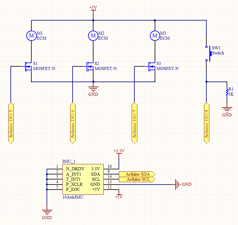
Connecting and programming the TA8050 DC motor controller with the Arduino microcontroller. The TA8050 is a versatile DC motor controller designed for use with microcontrollers, such as the Arduino. This controller allows for precise control of DC motors, making it...
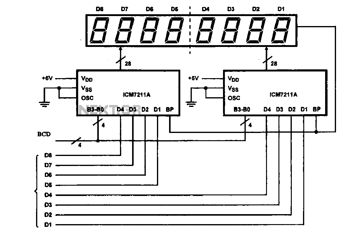
This circuit illustrates an 8-digit digital tube display driver, utilizing two ICM7211A integrated circuits. A BCD (Binary-Coded Decimal) to binary data signal is transmitted to the BO-B3 pins of the ICM7211A. The digital signals are divided into two groups...
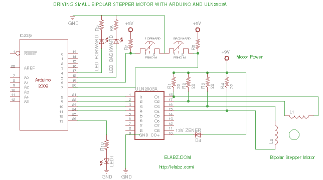
While preparing to disassemble several broken DVD-RW drives obtained from an eBay seller, the idea arose to create a testing platform for the bipolar stepper motors that would be salvaged from these drives. A collection of ULN2803AG Eight Darlington...