
hit the number
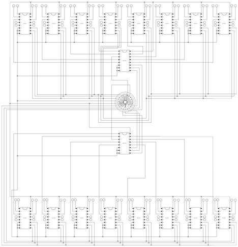
The circuit diagram indicates that the two small 8-pin ICs are the 555 timers, while the chip on the right is likely a 7-segment display decoder. The counter is located to the left of the decoder, and adjacent to it is a series of AND gates. The logic implemented sets the rows of the keypad high and checks the columns to identify any pressed keys. If no key is detected, it outputs %1111. It also verifies if the "random" pin is high, which indicates that a new random number is being generated; in this case, it outputs %1111 regardless of other conditions.
In the bottom-left section of the schematic, the logic for score increment detection is present. It checks if the current value is not %1111, meaning it only accepts a "correct button" result if a button is pressed. Upon a valid button press, it triggers a monostable timer (the adjacent 555 timer) to increment the score and initiate the random number generation process again. The timing delay is managed by another 555 monostable timer. A potentiometer adjusts the game speed, while a black push button serves as a master reset, clearing the score, restarting the main timer, and forcing a new random number generation.
For sound generation, two 555 timers (one operating at a fast rate and the other at a slower rate) are connected through an AND gate to produce a beeping sound for the "game over" notification. A switch is included to disable the sound, ensuring a quieter environment for others nearby.One PIC to act as a keypad driver though plus some primitive stuff to tie them together (when the time runs out disable the keypad and beep, when the correct button is pressed increment the score counter and regenerate). The random number generator is really bad. It relies on the inaccuracy of RC timing circuits! You have two 555 chips, one is set as a very fast astable (oscillator), the other as a much slower monostable (switches "on" for a while when the input is pulsed before switching itself off again). The output of both is ANDed and sent to the clock of a counter chip, so when the monostable`s input is triggered the counter counts up very quickly for a short space of time before the monostable switches off again and there`s your "random" number.
The `8` and `2` outputs of the counter are ANDed together and connected to the reset pin, so when the counter reaches 10 (8+2) it automatically resets to 0. Click for a circuit diagram. In the photo, the two small 8-pin chips are evidently the 555s, and I guess that the chip on the right is the 7-segment display decoder, the one to the left of that is the counter and the second left chip is a series of AND gates.
The logic is this; it sets the rows of the keypad high, then checks the columns until it finds one that`s connected, at which point it outputs the result. If no key is detected it outputs %1111. It also checks if the "random" pin is high (this signifies a new random number is being generated) and if so it outputs %1111 anyway.
In the bottom-left of the photo is the logic to detect when to increment the score (it checks if the current value isn`t %1111 - that is, it only accepts a "correct button" result if the button isn`t %1111, which indicates no button pressed). If all is hunky-dory it triggers a monostable to fire once (the 555 next to it) which increments the score, and triggers the random generator again.
The delay timing is, yep, another 555 monostable. The pot controls the speed of the game, the black push button is a master reset that clears the score, restarts the main timer and forces a new random number to be generated. Sound generation; two 555s (one very fast, one quite slow) through an AND gate give you a beep. beep. beep thing which would do for "game over". A switch to disable it retains the sanity of others in the room. 🔗 External reference
Related Circuits

The CP2128 is a low-noise, fixed-frequency step-up DC/DC converter designed for garden applications. It operates within an input voltage range of 2.7V to 4.5V and can generate a stable output voltage of 5V, with a maximum output current of...
This electronic game simulates a one-arm bandit game, appealing to electronics hobbyists. When toggle switch S1 is in the 'run' position, all segments of the 7-segment displays (DIS1 through DIS3) illuminate. Upon switching S1 from 'run' to 'stop', the...
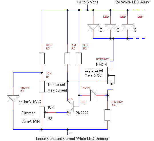
This simple linear circuit provides continuously variable regulated current (~25-400mA) from a 4-6 Volt source. The linear design is chosen for simplicity, reliability, ease of repair, and to avoid switching EMI in cave radios. The circuit requires only 0.2V...
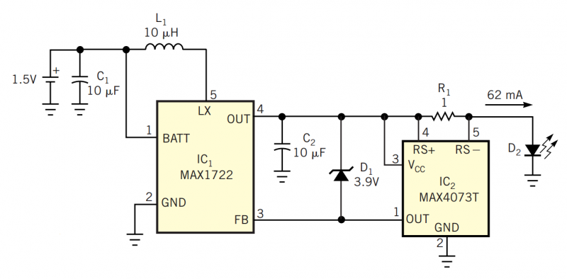
Although white LEDs are common in a variety of lighting applications, their 3 to 4V forward-voltage drop makes low-voltage applications challenging. Charge pumps and other ICs are available for driving white LEDs, but they generally don't work with the...
The moss tiles are part of a series of RAD experiments aimed at utilizing ceilings for healthier and more vibrant interiors. RAD identifies the ceiling as an underutilized area for creating interior landscapes. This space can be reclaimed by...

The Hitachi NP8C switching power supply circuit is illustrated in FIG. The Hitachi NP8C power models include CTP236, CEP320D, CRP350D, 450D, Furi HFC-236, 450, and Venus C37-401, C46-1, C563, among others. This circuit was widely used in early Chinese...