
how do sim card works on mobile phones

The SIM card serves as a critical component in mobile communication systems, enabling secure and efficient data management. The SIM control circuit plays a pivotal role in the operation of the SIM card, ensuring that data is accessed and transmitted correctly. This circuit generates the clock signal essential for synchronizing data transfer, which is crucial for maintaining communication integrity.
The connection between the SIM interface and the SIM control circuit is typically established through a series of pins that facilitate power and data communication. The data lines, often referred to as I/O lines, are responsible for transmitting data between the SIM card and the application processor. The integrity of these connections is vital; any disruption can lead to communication failures, highlighting the importance of robust design and construction practices in PCB layout.
The power supply voltage is another critical aspect of SIM card functionality. A stable voltage ensures that the SIM card can perform its operations without interruption. Any fluctuations in power supply can lead to erratic behavior or complete failure of the SIM card, emphasizing the need for reliable power management within the device.
The EMI-ESD filter incorporated into the design serves to shield the SIM circuitry from external interferences that could compromise its operation. By filtering out unwanted electromagnetic signals and providing protection against electrostatic discharges, this component enhances the overall reliability and durability of the mobile device. The design of the EMI-ESD filter is crucial, as it must effectively balance performance with size and cost considerations.
In summary, the SIM card's architecture, including its control circuitry, power management, and protective measures, is fundamental to its role in mobile communication. Understanding these components and their interactions is essential for designing effective mobile devices and troubleshooting related issues.A SIM Card also known as Subscriber Identity Module, A SIM is a Smart Card that can store data from a cellular phone. Those data like identity, location and phone number, network authorization data, personal security keys, contact lists and stored text messages.
Security features include authentication and encryption to protect data and prevent ea vesdropping. SIM Clock - this is a clock frequency signal that being synchronize to the digital data to create data signal in order transfer or sends and receive data information. In the layout the Sim Interface Connector connected directly to SIM Control Circuit. The SIM Control Circuit is the one the generates Clock frequency that triggers the SIM data storage, once the SIM is now being triggered, it is then now sends data information to the application processor to begin the process with.
The application processor is the one that gathered all data information from the SIM memory, initiate and activate it, if all information is in desired status. Those three particular lines of signal flows associated in the circuit shows how the synchronization is being applied.
If one of those lines being cut off the sending and receiving process will breakdown, and will result to SIM problem issues. The Power Supply Voltage through the SIM is also remain stable otherwise a lack of voltage will not activate the SIM to work.
In a picture below an EMI-ESD Filter has been added to protect the circuit to an Electro-static Discharge and Electro-magnetic Interference disorders. This type of SIM connection circuit is an advantage to mobile phone technician for troubleshooting SIM related problem issues.
Thus, type of particular EMI filter is very vulnerable and mostly create breakdown to the entire SIM connection. The EMI-ESD Filter is a highly integrated device designed to suppress EMI(Electromagnetic Interference) and RFI(Radio frequency Interference in a circuit.
This filter includes ESD protection circuitry which prevents damaging the mobile phone application when subject to ESD ( ElectroStatic Discharge) surges up to 15 kV. Here`s an example of how the the SIM data signal flow across the printed circuit board. Note: this is only shows where the signal flows from component to componentconnections. 🔗 External reference
Related Circuits
A design example for a portable data acquisition system is provided, which significantly simplifies the circuit design task. The portable data acquisition system is designed to capture, process, and store data from various sensors and input devices. This system typically...
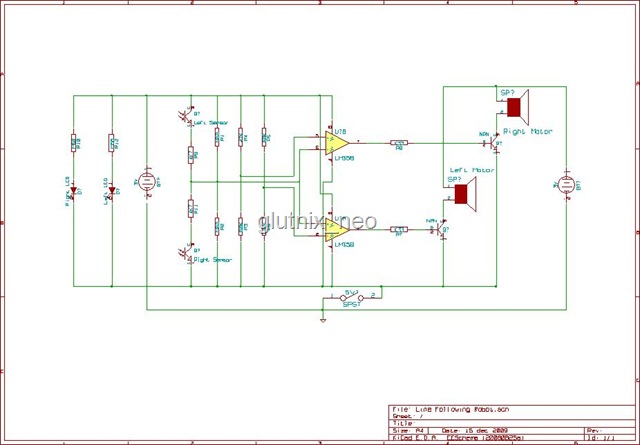
Originally, the tank cost around Php 400 but was later sold for approximately a hundred pesos less. Recognizing a great deal, the decision was made to purchase the toy. Opening the toy proved to be somewhat challenging. The track...
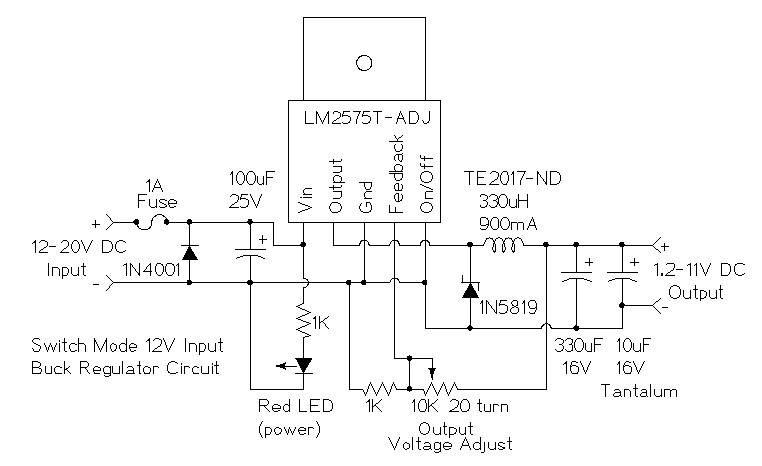
This is a simple buck mode switching regulator circuit diagram. This circuit is more efficient; switch mode regulators convert DC input voltage to pulses of high DC voltage. The DC pulses are used to charge a storage capacitor to...
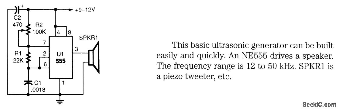
This basic ultrasonic generator can be built easily and quickly. An NE555 drives a speaker. The frequency range is 12 to 50 kHz. SPKRI is a piezo tweeter. The ultrasonic generator circuit utilizes the NE555 timer integrated circuit, which is...
This is a simple microphone preamplifier circuit that can be used between a microphone and a stereo amplifier. This circuit is suitable for connection with standard home stereo amplifier line/CD/aux/tape inputs. The microphone preamp can accommodate both dynamic and...
This document outlines a simple SWR (Standing Wave Ratio) protection circuit that can be easily constructed. The directional coupler and detector components are sourced from an old VHF SWR meter. It is advisable to replace the existing RF bypass...