


low cost audio headphone amplifier
#headphone amplifier
#audio amplifier
#PCB assembly
#electrolytic capacitors
#integrated circuit
#low cost
#stereo amplifier
#audio signal
#DIY audio
#electronics project
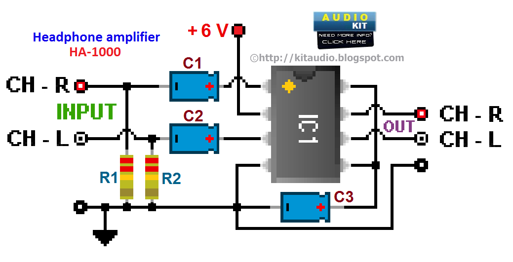
Description: Assembly is straightforward; simply follow the PCB overlay. Ensure that the integrated circuit and the electrolytic capacitors are oriented correctly. The electrolytic capacitors are polarized, marked with a + or - sign, and must be installed properly into the PCB. The integrated circuit and its socket feature a notch at one end, as indicated on the PCB overlay. If the integrated circuit lacks a notch, a dot will be present next to pin 1, indicating the same end.
The assembly process of the circuit board requires careful attention to the orientation of components, particularly the integrated circuit (IC) and electrolytic capacitors. The PCB overlay serves as a visual guide, providing clear markings that indicate the correct placement of each component.
Electrolytic capacitors are polarized components, which means they have a positive (+) and negative (-) terminal. It is crucial to install these capacitors in the correct orientation to prevent damage or malfunction. The PCB will have corresponding markings to assist in this process. Failure to connect the capacitor correctly may lead to short circuits or reduced performance.
The integrated circuit also has specific orientation requirements. The IC and its corresponding socket will typically feature a notch at one end. This notch is a critical reference point that aligns with the PCB layout. If the IC does not have a visible notch, a dot will be present next to pin 1, serving as an alternative orientation marker. Incorrect installation of the IC can result in malfunction or permanent damage to the component.
In summary, following the PCB overlay and paying close attention to the orientation of polarized components such as electrolytic capacitors and integrated circuits is essential for successful assembly. Proper installation ensures the circuit operates as intended and maintains reliability throughout its lifecycle.Assembly is very straight forward, just follow the PC board overlay. Make sure you get the integrated circuit and the electrolytic capacitors the correct way around. The electrolytic capacitors are polarized, they have a + or - marked on them and they must be inserted correctly into the PCB. The IC and socket have a notch at one end, which is mark ed on the PC board overlay. If there is no notch on the IC, there will be a dot next to pin 1, which is the same end.
The assembly process of the circuit board requires careful attention to the orientation of components, particularly the integrated circuit (IC) and electrolytic capacitors. The PCB overlay serves as a visual guide, providing clear markings that indicate the correct placement of each component.
Electrolytic capacitors are polarized components, which means they have a positive (+) and negative (-) terminal. It is crucial to install these capacitors in the correct orientation to prevent damage or malfunction. The PCB will have corresponding markings to assist in this process. Failure to connect the capacitor correctly may lead to short circuits or reduced performance.
The integrated circuit also has specific orientation requirements. The IC and its corresponding socket will typically feature a notch at one end. This notch is a critical reference point that aligns with the PCB layout. If the IC does not have a visible notch, a dot will be present next to pin 1, serving as an alternative orientation marker. Incorrect installation of the IC can result in malfunction or permanent damage to the component.
In summary, following the PCB overlay and paying close attention to the orientation of polarized components such as electrolytic capacitors and integrated circuits is essential for successful assembly. Proper installation ensures the circuit operates as intended and maintains reliability throughout its lifecycle.Assembly is very straight forward, just follow the PC board overlay. Make sure you get the integrated circuit and the electrolytic capacitors the correct way around. The electrolytic capacitors are polarized, they have a + or - marked on them and they must be inserted correctly into the PCB. The IC and socket have a notch at one end, which is mark ed on the PC board overlay. If there is no notch on the IC, there will be a dot next to pin 1, which is the same end.
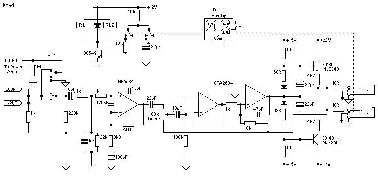
Hi-Fi Headphone Amplifier
This design for a headphone amplifier arose after the purchase of commercial equipment with separate pre and power amplifiers without a headphone output. Its advantages are low output impedance to drive several pairs of phones, the active gain stage is,...

10W Audio Amplifier with Bass-boost
10W audio amplifier with bass boost. High quality, very simple design. No preamplifier required. Circuit diagram: Parts: P1 22K logarithmic potentiometer (dual-gang).
This audio amplifier circuit is designed to deliver a power output of 10 watts, making it suitable for driving...
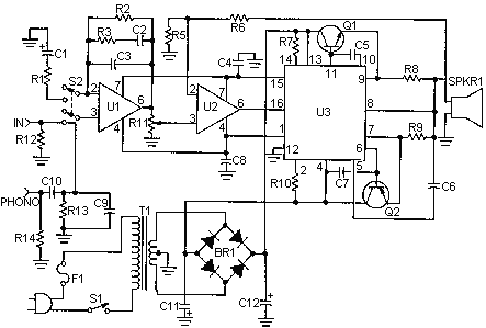
50 Watt Amplifier ICL8063
This is a handy, easy to build general purpose 50 watt amp. The amp has an input for a radio, TV, stereo or other line level device. It also has a phono input for a record player, guitar, microphone or...

headphone class a amplifier
A small headphone amplifier is a valuable device capable of driving multiple pairs of headphones. The headphone amplifier's task is simplified due to the relatively low output power requirements and the manageable load characteristics. Headphones generally have an impedance ranging...
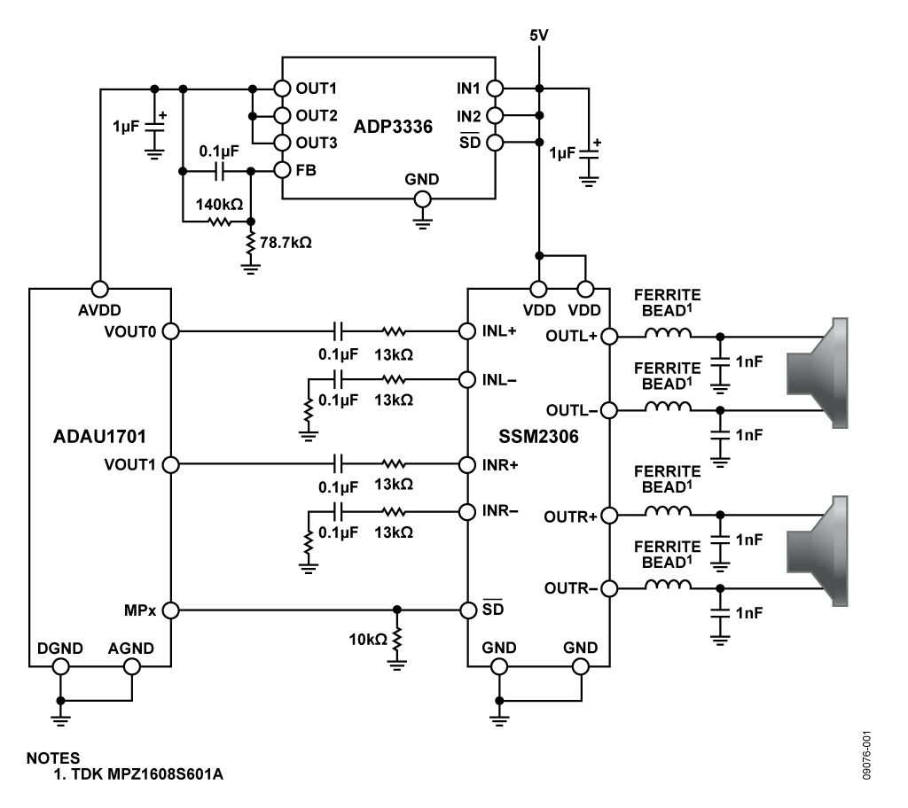
audio amplifier ssm2306
The SSM2306 is a fully integrated, high-efficiency, Class-D stereo audio amplifier designed to maximize performance for portable applications. The application circuit requires minimal external components and operates from a single supply voltage ranging from 2.5 V to 5.0 V. It...
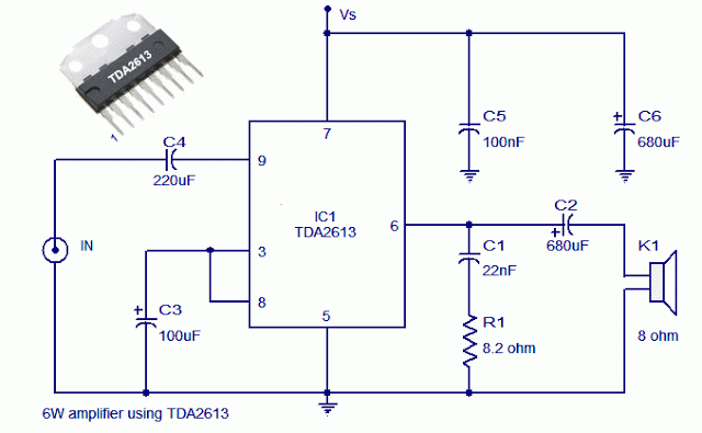
Reliable 6 Watt Hi Fi Audio Amplifier Using TDA2613
A 6-watt audio amplifier circuit utilizing the TDA2613 integrated circuit is presented. The TDA2613, produced by Philips Semiconductors, is a high-fidelity audio amplifier IC. This component is designed to be click-proof when switched on or off, resistant to short circuits,...
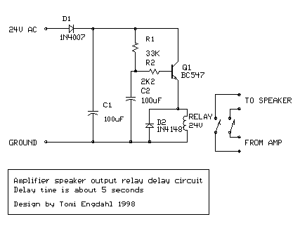
Audio amplifier output relay delay
This circuit was designed for an audio amplifier project to control the speaker output relay. Its primary function is to manage the relay that activates the speaker output in the audio amplifier, ensuring a delay of approximately 5 seconds after...
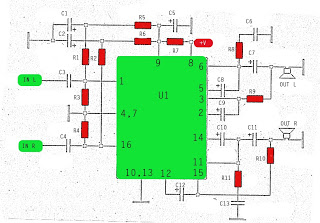
stereo stk013 audio amplifier circuit
The amplifier circuit utilizes the STK integrated circuit, similar to a previous design. This circuit features two inputs and two outputs, commonly known as a stereo amplifier. It is a power amplifier rated at 2 x 18 Watts with an...
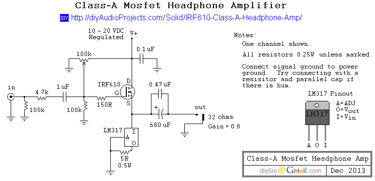
Class A Mosfet Headphone Amplifier
This is a simple and low-cost desktop headphone amplifier designed for office use. The amplifier concept is straightforward and adheres to a typical single-ended Class A circuit.
The desktop headphone amplifier utilizes a single-ended Class A design, which is known for...