
solar tracker system using lm358
No description available.
Related Circuits
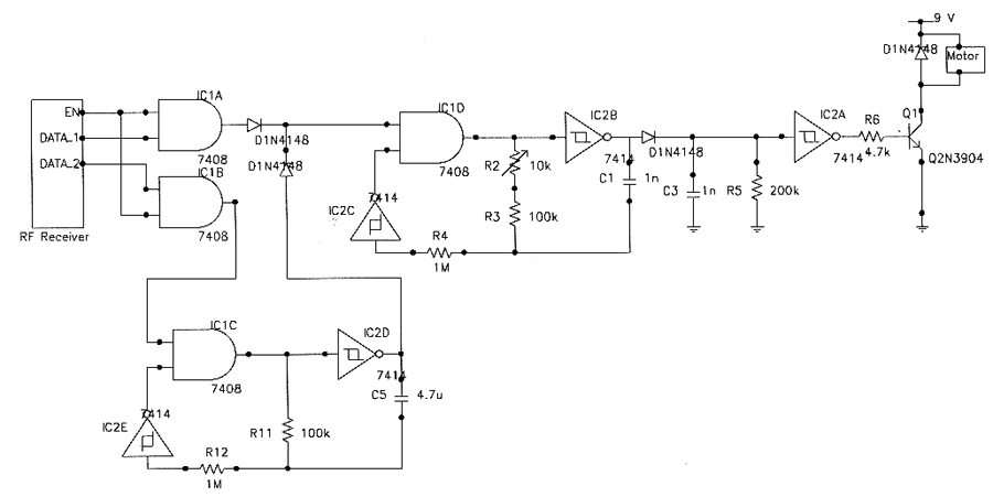
The TTY and the detector-transmitter unit are connected to separate phone jacks on the same line. When the ring sensor detects an incoming phone call, it activates the transmitter, which sends an RF signal to the receiver in the...
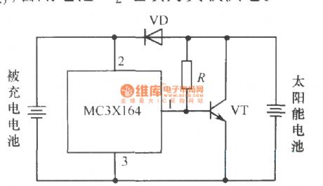
The following circuit illustrates a current-limited solar battery charger circuit diagram. This lead-acid or Ni-Cd battery charger circuit diagram utilizes solar energy to charge a 6-volt, 4.5 Ah rechargeable battery for various applications. It represents a straightforward solar battery...
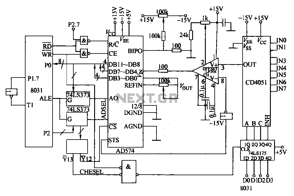
Converters and data sampling: A 12-bit A/D converter, AD574, is interfaced with an 8031 microcontroller circuit. Parameters are measured by a multi-way switch after a CD4051 strobe signal is sent to the sample/hold input device. The selection of the...
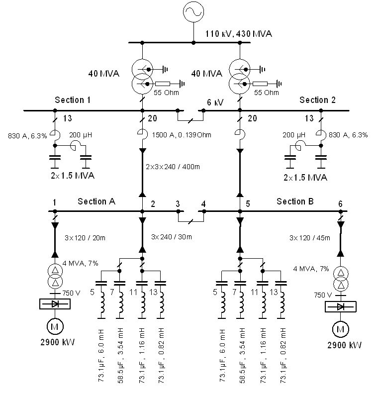
The vertical line indicates the instance of the 5th harmonic filter connection. The diagram illustrates the power system with the designed group of single-tuned filters for a system with a DC drive supplied by a 6-pulse controlled rectifier: PN...
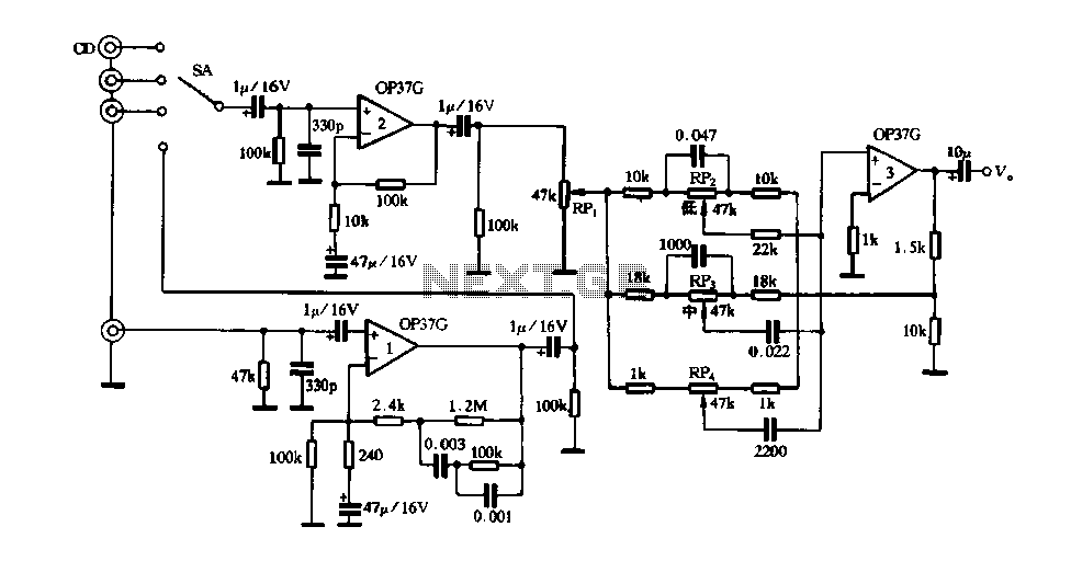
Figure 3 illustrates a circuit featuring the OP37, which is a multi-preamplifier configuration. The OP37 offers superior performance compared to the NE5534 integrated operational amplifier, as indicated in Table 3-3, which contrasts the parameters of both circuits. The table...
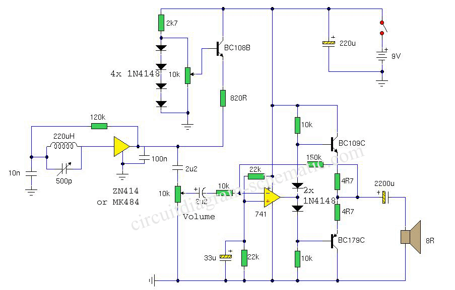
This is a circuit diagram of a portable AM radio receiver utilizing the ZN414 integrated circuit (IC), which has been replaced by the MK484, offering identical performance and pin configuration. The receiver is designed to operate within the medium...