
CLASSIC MINIMALIST AMPLIFIER

The described unit operates on a direct connection to the 120V AC power line, eliminating the need for a power transformer. This design simplifies the power supply circuit and reduces component count, which can enhance reliability and lower manufacturing costs. The filaments are configured in series, totaling 117 volts, which is achieved by combining four filament voltages: three at 35 volts and one at 12 volts. This series configuration ensures that all filaments receive the appropriate voltage for operation, contributing to efficient power distribution within the circuit.
The rectification of the AC voltage is accomplished using a 35W4 tube, which serves as a half-wave rectifier. This type of rectifier allows only one half of the AC waveform to pass through, effectively converting AC to DC. The output from the rectifier is then subjected to a three-stage RC (resistor-capacitor) filtering network, which smooths the rectified signal to provide a stable DC voltage. The B+ (anode voltage) for the output stage plates and screens is sourced from the second capacitor in this filter network, ensuring that the output stage operates with the necessary voltage for amplification. Meanwhile, the preamplifier and phase inverter stages receive their B+ from the third capacitor, allowing for separate regulation of the different stages of amplification.
The input signal to the amplifier is routed directly to a volume control potentiometer, which allows for adjustment of the signal level before amplification. Following the volume control, the signal passes through a variable high-pass filter, commonly referred to as the "Treble" control. This filter is designed to adjust the frequency response of the amplifier, enabling the user to tailor the treble frequencies to their preference. When the control is set to its minimum position, the filter response is approximately flat, providing a neutral sound output. This feature is crucial for users seeking to maintain the original tonal characteristics of the input signal while still having the flexibility to enhance higher frequency content as desired.The unit is powered directly from the 120 volt AC line, with no power transformers. Filaments are wired in series, with the total adding up to 117 volts (35 + 35 + 35 + 12). The 35W4 forms a half-wave rectifier, which is filtered by a three-stage RC network. The B+ for the output stage plates and screens are taken from the second capacitor, and the B+ for the preamp and phase inverter from the third capacitor in the filter. The input signal to the amplifier is applied directly to the volume control pot, from whence it passes through a variable high-pass filter (the "Treble" control). When the wiper is set to minimum, response is approximately flat (though actual fr 🔗 External reference
Related Circuits
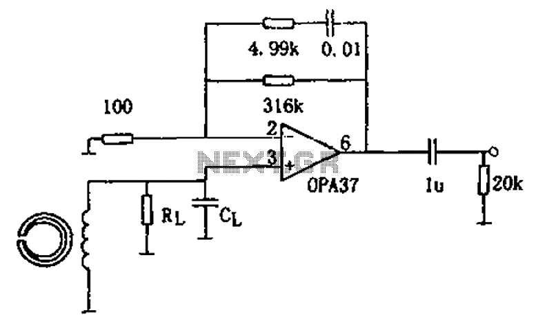
The circuit is a 90s common recorder head amplifier circuit that utilizes the ultra-low noise precision operational amplifier OPA37 as a preamplifier. This circuit is capable of providing standard NAB equalization. At a frequency of 1 kHz, it achieves...
This is a stereo power amplifier circuit that operates at up to 22W per channel, resulting in a total output of 2x22W. A few external components are required to support the main component, the TDA1554. A heatsink on the...
The circuit is a broadband amplifier designed to take video signals from a VCR and amplify them sufficiently to drive up to three monitors or TV sets, provided they can accept direct video signals. Additionally, it allows for recording...
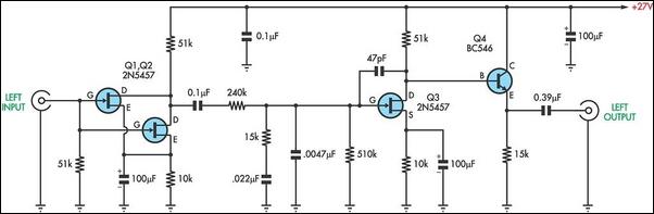
There are two types of preamplifiers for magnetic phono cartridges. The most common type includes an RIAA equalization network in the feedback loop, as described in the March 2002 issue of SILICON CHIP. The second type, previously used in...
This simple amplifier can be used for many things. Together with Equalization and (small) speakers good for the computer instance. The circuit uses IC TDA 2003 amplifier. This IC is in a TO-220 housing, and has 5 pins. Decoupling...
This reference design demonstrates the MAX98400 Class D audio amplifier in a stereo audio docking station application. The demo box is a powered speaker dock that drives a speaker system consisting of 2-inch satellite speakers and a 5-inch subwoofer. The...