Coin-flipper

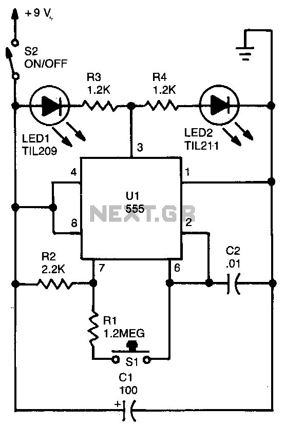
The circuit is a 555 astable circuit that controls two LEDs, LED1 and LED2. LED2 is activated when the output of U1 is high, while LED1 turns on when the output is low. As U1 oscillates, LED1 and LED2 alternate switching on as the output of U1 changes state. The value of resistor R1 is significantly higher compared to R2, resulting in a square wave output with a nearly one-to-one mark/space ratio. Additionally, when switch S1 is released, the circuit is broken, and U1 retains its current output state.
The described circuit employs a 555 timer configured in astable mode, which generates a continuous square wave output. This oscillation is fundamental for driving the two LEDs, LED1 and LED2. The switching behavior of the LEDs is dependent on the output state of the 555 timer, which alternates between high and low states.
The resistors R1 and R2, along with the timing capacitor (not explicitly mentioned), set the frequency of oscillation and the duty cycle of the output waveform. In this configuration, R1 is chosen to have a much higher resistance than R2, which results in a nearly equal mark and space time in the output signal. This means that the LEDs will have a similar amount of time illuminated and off, creating a visually balanced effect.
The inclusion of switch S1 allows for manual control over the circuit operation. When S1 is pressed, it completes the circuit, allowing the 555 timer to function normally. Upon releasing S1, the circuit opens, and the 555 timer latches the last output state. This feature can be useful for applications where it is necessary to maintain the last visual output of the LEDs without requiring continuous power to the switch.
In summary, this circuit is a simple yet effective design for alternating LED indicators using a 555 timer in astable mode, demonstrating basic principles of electronic timing and control. The careful selection of resistor values and the inclusion of a manual switch enhance the functionality and versatility of the circuit.The circuit is basically a 555 astable circuit that divides two LEDs, LEDl and LED2. LED2 is switched on when the output of Ul is high, and LEDl is activated when its output is low. When Ul oscillates, LEDl and LED2 switch on alternately as the output of Ul switches from state to state. Resistor Rl"s value is high in comparison to R2, so the waveform at the output is a square wave with a mark/space ratio of nearly one-to-one.
When you release Sl, you break the circuit and Ul latches whatever the output state happens to be at the time.