
Compact 100W power amplifier circuit

The design of the tube amplifier circuit featuring the 2SA1227A and 2SC2987A transistors emphasizes the importance of efficient thermal management and power supply design to optimize performance. The double tube parallel output stage not only increases the output power but also enhances the overall fidelity of the amplifier. The choice of a 45V supply voltage serves to balance the need for high power output with thermal considerations, as excessive voltage can lead to increased heat generation, potentially affecting the reliability and lifespan of the tubes.
The circuit configuration allows for flexibility in power supply arrangements, accommodating both shared and separate power supplies for the pre-amplifier and output stages. This modular approach can enhance the performance of the amplifier by minimizing interference between stages and ensuring stable operation under varying load conditions.
In terms of frequency response, the amplifier circuit is well-suited for audio applications, with low harmonic distortion across a range of frequencies, indicating high fidelity in sound reproduction. The measured harmonic distortion values suggest that the circuit is capable of delivering clear and accurate audio signals, making it suitable for high-quality audio amplification. The performance metrics detailed in Table 2-35 provide valuable insights into the operational characteristics of the amplifier under different conditions, guiding engineers in the design and optimization of similar tube amplifier circuits. By the pLPC1342V and NE (two company names and fever on the tube amplifier circuit 2SA1227A 2SC2987A composed of maximum output power up to 120W, the cutoff frequency up to 500 MHZ. Its up to the state collector output current f 12Ao circuit shown in Figure 2-126 o shown by the ring shows that the output stage of the circuit is double tube parallel output, the purpose is to increase the output power. circuit voltage using 45V, operating voltage can be increased to improve the output power, but consumption and tube amplifier tube heat also increased, so the output power to meet the needs, the supply voltage should be as low as possible.
for 2SC2987A/2SA1227A composition amplifier circuit, the final stage of the power supply is preferably not more than 45Vo can pre-ppC1342V the last stage of a common set of power, you can also use a separate set of power level before and after the separate power supply, pre-regulated power supply can be used before and after class when sharing a set of power, you can figure a and b, c and d. linked to table 2-35 lists the time 1342V and 2SC2987A, 2SA1227A amplifier circuit composed at different power supply voltages and different forms of testing this circuit found: it has excellent frequency response, when the output power 1w (1 load 8.
the letter source frequency number changes from 10H to 100kHt, no transition curve characteristic base rate move; fo at 400kHz, the curve fell 2d30 rate machine fidelity is also very good, when when the output power of loow, lkHz: harmonic distortion of the signal 0 012%, 100HZ harmonic distortion of the signal 0.008%, harmonic distortion signal 100kHz 0.005% o.
Related Circuits
If you want to try a higher voltage with your pedals, try this simple and easy voltage doubler circuit which uses an ICL7660 CMOS Voltage Converter Chip. I have found that JFETs such as the J201 sound much better...
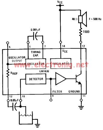
The LM1830 low-level detector can utilize an audio indication (speaker) or a visual indicator (LED - light-emitting diode) that activates when the level is too low. This low-level detector circuit generates a 500 Hz audio signal when the level...
A sawtooth wave generator circuit using a 555 IC is presented in the article below. The frequency equation is provided with the supply voltage Vcc. The sawtooth wave generator circuit utilizing a 555 timer integrated circuit (IC) is a fundamental...
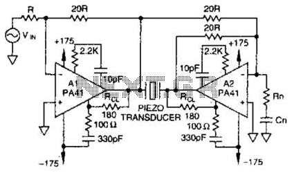
Using a PA41 from Apex Microtechnology, this monolithic amplifier is capable of 350-V operation and delivers 660 V peak-to-peak in a bridge circuit. The PA41 is a high-performance monolithic amplifier designed for applications requiring high voltage and high power output....
The LM1036 is a DC-controlled circuit designed for adjusting bass, treble, balance, and volume in stereo applications, particularly in car radios, televisions, and audio systems. An additional control input enables the implementation of loudness enhancement. Four control inputs facilitate...
This simple circuit can be used to charge a pair of AA or AAA-sized cells using solar energy. It has been utilized to maintain the operation of devices such as a Palm Pilot and a Walkman radio continuously. This...