Complementary-output-variable-frequency-inverter

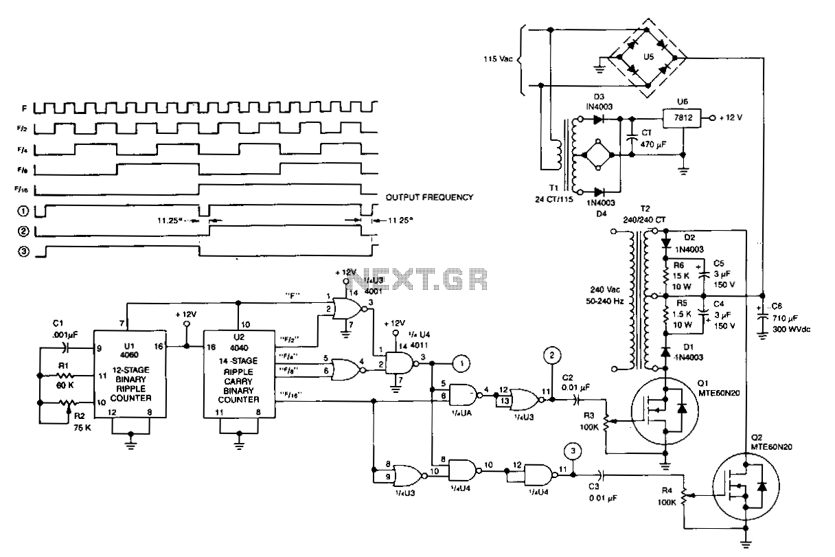
U1 is a 4060 12-stage binary ripple counter that operates as a free-running oscillator, with its frequency of oscillation calculated as 1/2.2 CIR2. The output from U1 is fed into U2, a 14-stage binary ripple counter that generates square-wave outputs at frequencies of 1/2, 1/4, and 1/8 of the clock frequency. These signals are combined in U3 and U4 to deliver complementary drive signals for transistors Q1 and Q2. The outputs from U3 and U4 are AC-coupled to Q1 and Q2 through capacitors C2 and C4, respectively. Resistors R3 and R4 are utilized to adjust the gate drive to Q1 and Q2. Q1 and Q2 alternately draw current through opposing sides of the primary winding of transformer T2, thereby synthesizing an AC input voltage at a specified frequency. It is important to note that only one side of the primary winding of T2 is driven at any given time, which results in the maximum power output being limited to half of the transformer's rated capacity.
The circuit employs a 4060 binary ripple counter (U1) to generate a stable oscillation frequency, which is determined by the external components connected to it. The oscillation frequency is crucial for applications requiring precise timing and frequency generation. The output from U1 drives a second binary ripple counter (U2), which further divides the frequency into lower ranges, producing square-wave outputs. These outputs are essential for various digital applications and can be used to control other components in the circuit.
The combination of U3 and U4 serves to create complementary signals that ensure that Q1 and Q2 operate in a push-pull configuration. This configuration is effective for driving loads that require alternating current. The AC coupling through capacitors C2 and C4 allows for isolation of DC components while passing the AC signals effectively to the gates of Q1 and Q2, ensuring that the transistors switch appropriately without being affected by any DC bias.
Resistors R3 and R4 play a critical role in fine-tuning the gate drive signals to Q1 and Q2, allowing for optimal switching performance. This adjustment is vital for ensuring that the transistors operate efficiently, minimizing heat generation and maximizing performance.
The transformer T2 is central to the circuit's operation, as it steps up or steps down the voltage based on the primary winding's configuration and the load requirements. By driving only one side of the primary winding at a time, the circuit effectively manages power output, ensuring that it does not exceed the transformer's rated capacity, which is a crucial design consideration for maintaining reliability and preventing damage to the components involved.U1 is a 4060 12-stage binary ripple counter that is used as a free-running oscillator; its frequency of oscillation is: 1/2.2 CIR2. The output of U1 is applied to U2, a 14-stage binary ripple counter that provides square-wave outputs of lfz, 1/4, "is, and "lls of the clock frequency.
These signals are combined in U3 and U4 to provide a complementary drive for Q1 and Q2. Outputs from U3 and U4 are ac-coupled to Q1 and Q2 via C2 and C4, respectively. R3 and R4 adjust tbe gate drive to Q1 and Q2. Q1 and Q2 alternately draw current through opposing sides of the primary to synthesize an ac input voltage at a given frequency. Only one side of the primary of T2 is driven at one time, so maximum power output is half of the transformer rating.