
Construction of the Mk1 Receiver

The remote control receiver circuit is designed around a 433MHz UHF radio receiver module, which is responsible for receiving signals from a remote transmitter. The integration of a decoder chip is crucial for interpreting the received data, allowing for effective communication between the remote control and the receiver. The BASIC Stamp microcontroller serves as the central processing unit, managing the overall functionality of the circuit and providing a user-friendly programming environment.
Power consumption is a critical aspect of this design. The receiver operates at a nominal current of 8.5mA, with additional current draw depending on the number of LEDs activated—1.5mA per LED. In practical scenarios, the total current consumption typically ranges from 13mA to 16mA, depending on the operational state of the LEDs. When a button on the remote is pressed, the receiver experiences a slight increase in current consumption, approximately 0.2mA, due to the processing of the received signal.
To enhance energy efficiency, the circuit employs a 'power saving' mode activated by the PBASIC nap instruction. This mode effectively reduces the current consumption to 4mA by turning off all LEDs, thus prolonging the battery life. The design anticipates a battery life of approximately 30 hours under typical usage conditions, making it suitable for applications where battery replacement is inconvenient.
Overall, this remote control receiver circuit combines a robust design with efficient power management, making it a practical solution for wireless control applications. The choice of components and their configuration ensures reliable performance while maintaining ease of use and programming flexibility.The remote control receiver is a custom design based on a pre-built 433MHz UHF radio receiver, a decoder chip and a BASIC Stamp. The Stamp is expensive, but easy to work with. The receiver requires 8.5mA, plus 1.5mA for each LED (individual or segment) that is lit for a maximum of up to 23mA.
In practice it is between 13 and 16mA. Pressing a button on the remote transmitter causes the receiver to consume an extra 0.2mA. In the `power saving` mode the PBASIC `nap` instruction is used in combination with turning all the LEDs off to reduce power consumption to 4mA. The battery should last about 30 hours of on-time. 🔗 External reference
Related Circuits
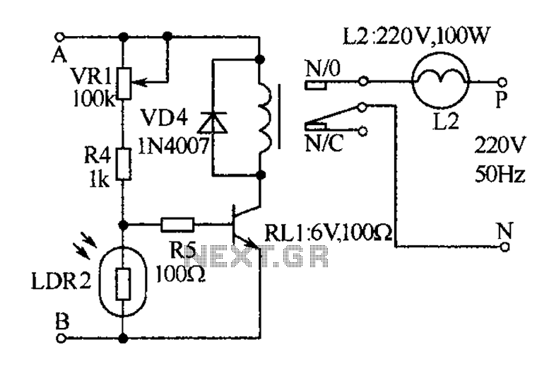
The receiver, as depicted in the figure, assists patients in avoiding missed audio signals during the daytime. The receiver operates independently, and the lighting will automatically turn off. At night, the lighting signal receiver activates simultaneously with the patient's...
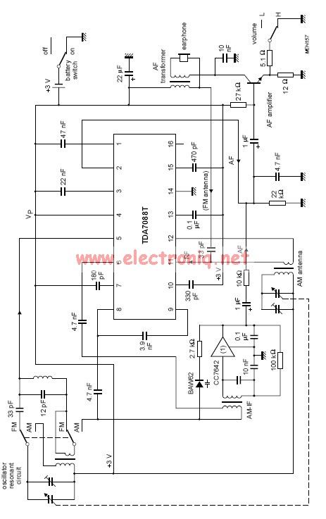
The TDA7088 incorporates a frequency-locked loop (FLL) system with an intermediate frequency (IF) of approximately 70 kHz. This circuit can be powered using a 3-volt battery cell or a regulated power supply. The TDA7088 is designed for use in various...
This circuit enables the generation of audio musical notes that can be heard from a distance of up to 10 meters. It consists of two main components: an infrared (IR) music transmitter and an IR music receiver. The IR...
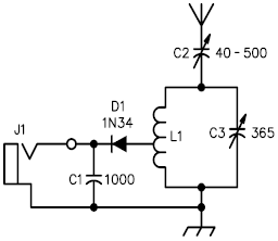
A crystal radio receiver is a very simple radio receiver that requires no battery or external power source, operating solely on the energy harvested from radio waves through a long antenna. A crystal radio receiver is a passive radio receiver...
The circuit demonstrates the application of the ZN414 integrated circuit (IC) to create a compact AM radio receiver. The ZN414 IC is a combination of a transistor and a tuned radio frequency (TRF) circuit. The ZN414 IC is specifically designed...
There is a vast array of TX and RX modules available for microcontrollers. The least expensive option identified was priced at $9.99, which is reasonable, although there are memories of encountering FM receiver modules in the past. The TX (transmitter)...