
control solid state relays up to 50

The project centers around a microcontroller-based control system capable of managing multiple solid-state relays (SSRs). Each relay can be activated or deactivated independently, allowing for versatile control of various devices, making it suitable for educational purposes in electronics and embedded systems. The use of solid-state relays provides advantages such as faster switching times and increased durability compared to mechanical relays.
The system utilizes an LED indicator for each relay to display its status, which can be replaced with optical isolators for better isolation and protection of the microcontroller from high-voltage circuits. The command system implemented allows for straightforward control, where each relay is accessed by a specific command, enhancing the ease of use and programming flexibility.
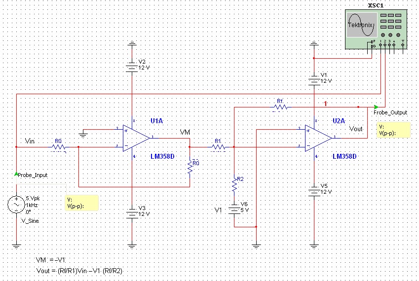
The project includes detailed schematics for interfacing the 8051 microcontroller with the solid-state relays, ensuring proper operation and control. The 8051 architecture is leveraged for its robust capabilities, including sufficient input-output lines to manage multiple relays. The integration of additional components, such as a scrolling dot matrix LED display, allows for real-time status updates and visual feedback for the user.
Moreover, the project explores the use of GSM technology for remote control applications, showcasing a modern approach to automation. The inclusion of solenoid valves illustrates the control of various types of loads, expanding the practical applications of the project. The MOC3010 optoisolator is also highlighted for its role in safely interfacing the microcontroller with high-voltage components, ensuring the integrity of the microcontroller while managing external devices.
Overall, this project provides a comprehensive platform for learning and experimentation in microcontroller applications, relay control, and interfacing techniques, making it a valuable resource for students and hobbyists in the field of electronics.This project is developed to control up to 50 solid state relays individually. The project is good learning material for students who which to expand the input output lines of microcontroller and want to control many devices. 2. The ON or OFF status of each external hardware device is currently shown with the help of LED, which will be replace wit
h optical isolator to interface the relays or other high load device. n_ _ or N_ _ i. e. here n or N stands for "ON" and at blank spaces put the number 01 to 50. so we can say that to turn on the led number 5, command will be n05 or N05. circuit diagram of 8051 interfacing with relay coils, relay switch atmel microcontroller, scrolling dot matrix led display using 8051, circuit diagram for line tracer using micro controller 8051, microcontroler comanda motor cc. schematic diagram sms relay control board usig gsm technology and microcontrolle 16f877 10 valvulas solenoides how to use moc3010
🔗 External reference
Related Circuits
This article was previously published, but the intention is to spread the idea further, potentially inspiring new concepts. An improved version was being developed using an ULN2803A instead of multiple BC547B transistors and optional Zener diodes to ensure that...
All naturally occurring phenomena such as sound, temperature, and pressure are analog in nature. To enable a microcontroller to read analog signals for the analog-to-digital conversion process using a built-in analog-to-digital converter (ADC), it is essential to condition the...
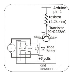
To control the motor, an H-bridge will be utilized in conjunction with a double-pole double-throw (DPDT) relay, as illustrated in the schematic below. For further details, additional resources are available. The proposed circuit employs an H-bridge configuration to facilitate bidirectional...
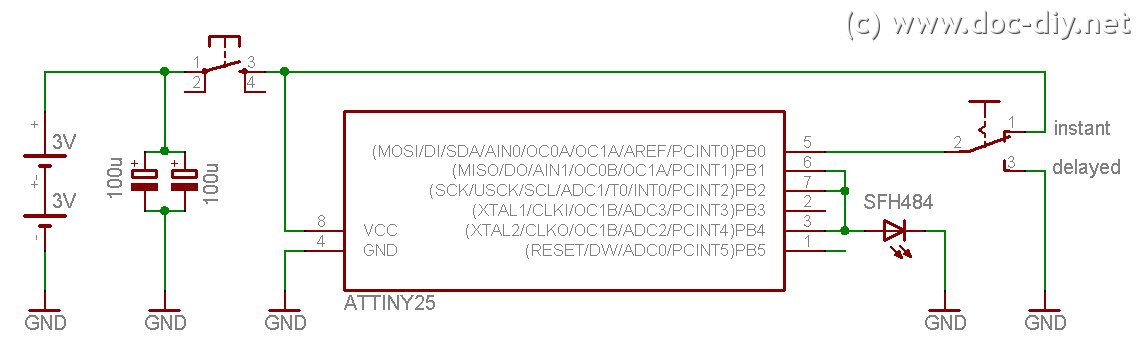
This site explains the process of constructing a low-cost DIY Canon RC-1 infrared remote control clone utilizing an AVR microcontroller. The project involves creating a remote control that mimics the functionality of the Canon RC-1, which is used for triggering...
The LM1036 is a DC-controlled circuit designed for adjusting bass, treble, balance, and volume in stereo applications, particularly in car radios, televisions, and audio systems. An additional control input enables the implementation of loudness enhancement. Four control inputs facilitate...
This project allows for the control of two wheels or tracks from a PC serial port without any wired connections. The system operates at 2400 baud. A Basic Stamp microcontroller is utilized, with the Basic Stamp I being used...