
Conversation Recorder

The circuit operates by detecting the state of the telephone handset. When the handset is lifted, a change in voltage occurs across the telephone line, which is utilized to trigger the operation of the tape recorder. Resistors R1 and R2 form a voltage divider network, which reduces the voltage from the telephone line to a safe level suitable for the MIC-IN input of the tape recorder. The specific values chosen for R1 and R2 are crucial, as they must match the input impedance of the tape recorder's MIC-IN socket to ensure optimal signal transfer without distortion.
Capacitor C1 serves an important function by blocking any direct current (DC) component from the telephone line, allowing only the alternating current (AC) audio signals to pass through to the tape recorder. This ensures that the recording is free from unwanted DC offsets that could affect the audio quality.
Relay RL1 plays a pivotal role in the circuit by acting as a switch that controls the power to the tape recorder. When the handset is lifted, the relay is energized, closing the circuit and powering the tape recorder. Conversely, when the handset is placed back, the relay is de-energized, cutting off power to the tape recorder, thus stopping the recording.
The circuit is designed to operate with a standard telephone line voltage of 48 volts in the on-hook condition, which is typical for many residential telephone systems. The design can be adapted for different tape recorder models by adjusting the resistor values and ensuring compatibility with the specific input requirements of the MIC-IN socket. This automatic switching mechanism enhances convenience by allowing users to record audio without manual intervention, thus streamlining the recording process.This circuit enables automatic switching-on of the tape recorder when the handset is lifted. The tape recorder gets switched off when the handset is replaced. The signals are suitably attenuated to a level at which they can be recorded using the MIC-IN socket of the tape recorder. Resistors R1 and R2 act as a voltage divider. The voltage appearing across R2 is fed to the MIC-IN socket of the tape recorder. The values of R1 and R2 may be changed depending on the input impedance of the tape recorders MIC-IN terminals.
Capacitor C1 is used for blocking the flow of DC. The second part of the circuit controls relay RL1, which is used to switch on/off the tape recorder. A voltage of 48 volts appears across the telephone lines in on-hook condition. 🔗 External reference
Related Circuits
A wife was working on a doctoral dissertation that involved fieldwork, specifically personal interviews in various settings. The challenge was to find a suitable technical solution for recording these interviews. Passing a tape recorder or microphone back and forth...

This circuit is based on the UM5100, which can record speech into digital memory and then play it back. The device is designed for use with static RAMs up to 256K bits or with EPROMs or ROMs for playback...
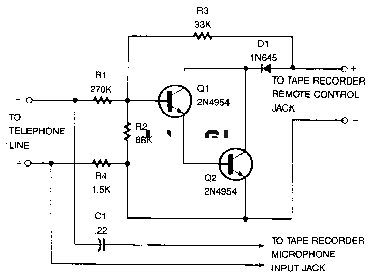
This recorder can be connected to telephone lines almost anywhere, and it does not require an external power source. The switch terminals of the tape recorder are connected to a pair of transistors configured as Darlington pairs, which are...
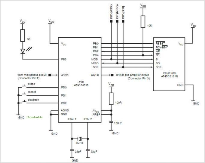
The Z86E02 is one of ZiLOG's most popular Z8 One Time Programmables (OTPs). It features a 512-byte EPROM, 61 bytes of RAM, 14 I/O ports, a Watch-Dog Timer, Power-On Reset, a Low-Voltage Protection circuit, and an additional Timer. Notable...
The ISD1000A is a Direct Analog Storage device which allows you to store 20 seconds worth of voice data on an IC chip which can be played back anytime. The data stored will stay in memory even if the...
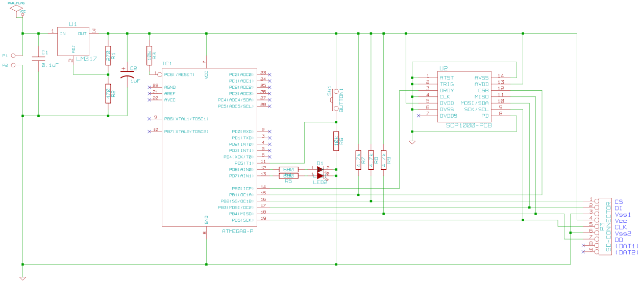
This circuit is designed to record the altitude of a remote-controlled (R/C) plane. The recorded data is stored on an SD card. It utilizes an ATmega8 microcontroller and a SCP1000 chip to measure temperature and, more importantly, atmospheric pressure....