
Converting an analogue signal to a digital signal

To connect an analogue signal to a PIC (Peripheral Interface Controller), a suitable interface circuit is required to ensure accurate signal processing and compatibility with the microcontroller's input specifications. The following outlines the essential components and considerations for designing this interface.
1. **Signal Conditioning**: The analogue signal, which may vary in amplitude and frequency, often requires conditioning to fit within the input range of the PIC. This may involve amplification, filtering, and level shifting. An operational amplifier (op-amp) can be used to amplify low-level signals, ensuring they are within the acceptable input range of the PIC's analogue-to-digital converter (ADC).
2. **Voltage Reference**: The PIC typically has a specified reference voltage for its ADC, which is usually set to the maximum input voltage that can be accurately measured. If the analogue signal exceeds the reference voltage, it can lead to saturation and inaccurate readings. A voltage divider can be employed to scale down higher voltage signals to the appropriate level.
3. **Filtering**: To eliminate noise and ensure that only the desired frequency components of the signal are processed, a low-pass filter can be implemented. This filter can be constructed using passive components (resistors and capacitors) or active components (op-amps).
4. **Protection Circuitry**: To protect the PIC from over-voltage situations, it is advisable to include clamping diodes or a transient voltage suppressor. This prevents damage to the microcontroller in cases of unexpected voltage spikes.
5. **Connection to the PIC**: The conditioned analogue signal is then connected to one of the ADC input pins of the PIC. It is vital to ensure that the ground of the signal source is common with the ground of the PIC to avoid ground loop issues, which can introduce errors in the measurements.
6. **Software Configuration**: The PIC's firmware must be configured to read the analogue signal. This involves setting the appropriate ADC channel, configuring the ADC clock, and implementing the necessary code to sample and convert the analogue signal into a digital value for processing.
By carefully designing the interface circuit with these considerations, accurate and reliable analogue signal processing can be achieved, enabling effective interaction between the analogue world and the digital capabilities of the PIC microcontroller.his chapter shows how to connect an analogue signal to a PIC. An analogue signal is similar to a sine wave and is generally less than 5v (5,000mV) in amplitude. Low-level signals are generally expressed in mV, to make them instantly recognisable and easy to talk about. 🔗 External reference
Related Circuits
500 Series immersion temperature probe, NTC, 100,000 Ohm, ±1.5 °C [±2.7 °F] tolerance, 10 °C to 260 °C [50 °F to 500 °F] accuracy, stainless steel, bullet housing, flying leads (two), 26 gauge Teflon insulation, 4,267 mm [168 in]. The...
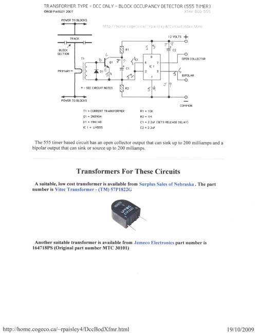
This article falls under the "you can do it too" category. It is not as difficult as one might imagine for the average model railroader, especially with the information available online and articles like this to guide the process....
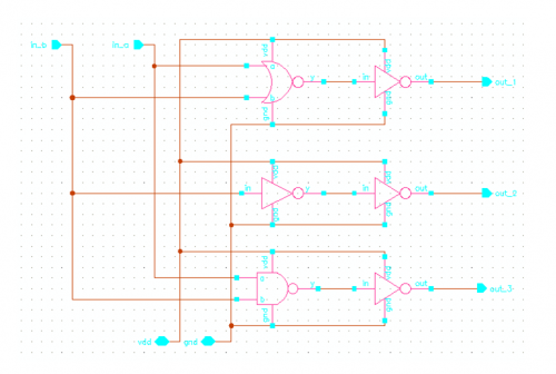
INTRODUCTION Digital to analog converters are one of the most commonly employed circuits in many applications involving digital video, signal processing, and testing. Digital to analog converters (DACs) serve a critical role in modern electronic systems by converting digital signals,...
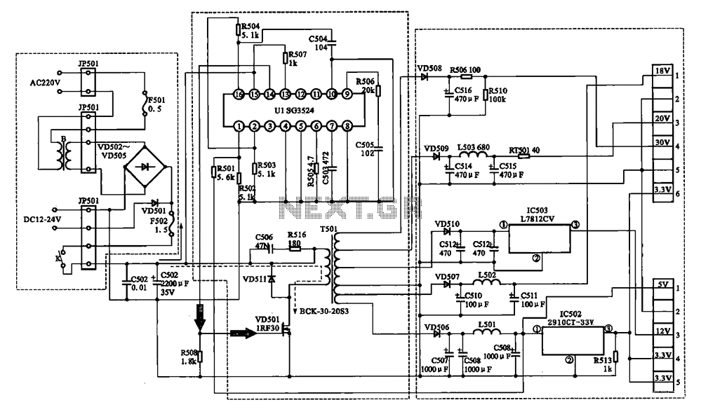
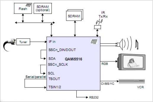
The Changhong DVB-2000 digital satellite receiver features a switching power supply circuit. This circuit primarily comprises a power input section, an oscillation switching circuit, and a DC output section. The power input circuit receives 22V AC from a step-down...

Usually we see Digital clock on LCD or 7 segment. But, this AVR Digital Clock which is designed by Ficara Emilio displayed on Oscilloscope. The project uses ATtiny 2313 as the main controller. What an interesting microcontroller project. Source...
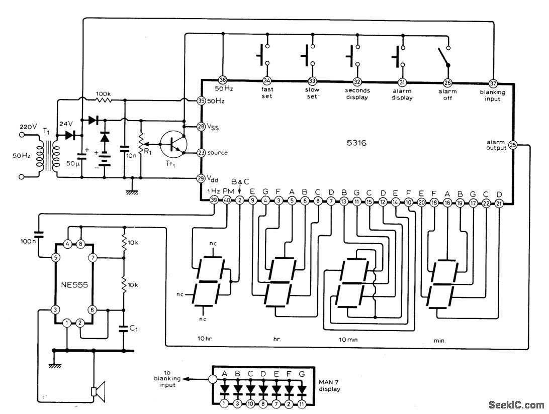
The circuit utilizes the MM5316 alarm-clock integrated circuit (IC), which is originally intended for driving LCD or fluorescent displays. In this implementation, it has been adapted for use with LED display diodes. The system is designed to operate on...