
Courtesy light extender

The circuit operates by utilizing a simple yet effective design to control the interior light of a vehicle through the door switch mechanism. The single-pole switch is strategically grounded, allowing for a straightforward completion of the circuit when the door is opened. This design is versatile, accommodating both negative and positive ground systems in vehicles by adjusting the connections accordingly.
When the door is opened, the switch closes, leading to the discharge of capacitor C1 through diode D1. This rapid discharge brings the voltage across C1 to zero, initiating the charging process once the switch is opened. Resistors R1 and R2 play a critical role in controlling the charging rate of C1, allowing for a gradual increase in voltage across transistor Q2. The emitter follower configuration of Q1 and Q2 ensures that Q2 can effectively buffer the output, maintaining a stable voltage level that keeps the lights illuminated.
The timing of the light activation is determined by the capacitance of C1. By selecting an appropriate value for C1, the circuit can be fine-tuned to provide a desired light duration. The design allows for a light level that is perceptible for about four seconds before gradually dimming over the next six seconds until the lights are completely off. This gradual reduction in light intensity enhances the user experience by preventing abrupt changes in lighting, which can be jarring in a vehicle environment.
In summary, this car door switch circuit exemplifies a practical application of basic electronic components to achieve a functional and user-friendly lighting system in vehicles. The ability to adjust C1 to accommodate different vehicle types and configurations adds to the circuit's versatility and effectiveness.Most car door switches are simply single-pole switches, with one side grounded. When the door is opened the switch grounds the other line thus completing the light circuit. In a car where the negative terminal of the battery is connected to the chassis, the negative wire of the unit (emitter of Q2) is connected to chassis the positive wire (case of 2N3055) is connected to the wire going to the switch. In a car having a positive ground system this connection sequence is reversed. When the switch closes (door open), CI is discharged via D1 to zero volts, and when the switch opens, Cl charges up via R1 and R2.
Transistors Ql and Q2 are connected as an emitter follower (Q2 just buffers Ql) therefore the voltage across Q2 increases slowly as Cl charges Hence Q2 acts like a low resistance in parallel with the switch and keeps the lights on. The value of Cl is chosen such that a useful light level is obtained for about four seconds; therefore the light decreases until in about 10 seconds it is out completely. With different transistor gains and with variation in current drain due to a particular type of car, the timing may vary hut may be simply adjusted by selecting Cl.
Related Circuits
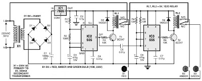
This is a simple traffic light controller that can be used to teach children the basics of traffic light rules. The circuit employs commonly available electronic components and consists of rectifier diodes (1N4001), a 5V regulator (7805), two timer...

Two operational amplifiers are utilized in a bridge circuit configuration to detect high and low light levels. Potentiometer R2 adjusts the dark level, while resistor R1 controls the light level. Resistor R3 is configured so that approximately 1A of...
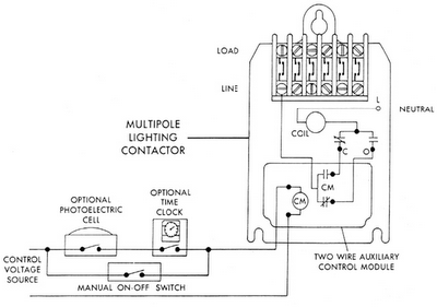
Sensors for lighting controls include photoelectric sensors and presence detectors. Photoelectric sensors typically switch lighting on at dusk and off at dawn, with adjustable settings for sensitivity to light levels. They feature built-in time delays to prevent unwanted switching...
The circuit illustrated in the figure utilizes 14 bi-color (red and green) LEDs, each featuring three terminals. This configuration enables the creation of various dancing color patterns, as each LED can display three distinct colors. The middle terminal (pin...
Most cars do not have delayed interior lights. The circuit presented can rectify this issue by gradually switching the interior lights of a car on and off. This feature facilitates tasks such as locating the ignition keyhole after the...
The circuit shown here is used to switch on a lamp when the telephone rings, if the ambient light is insufficient. The circuit uses only two ICs and it can be implemented very easily. A light dependent resistance (LDR),...