
Crystal Radio II

No description available.
Related Circuits
Nearly all AM radio manufacturers utilized this specific circuit from approximately 1948 to 1963. There is a growing interest in collecting these radios as antiques. Credit for the creator of this figure and caption is sought, but the source...
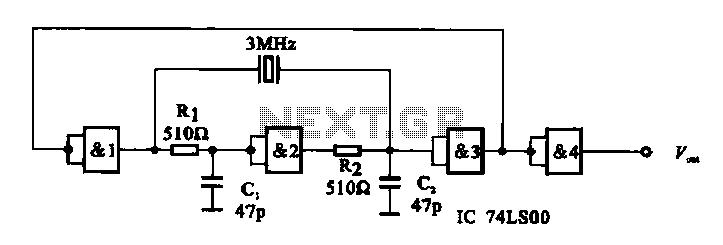
A crystal oscillator circuit is composed of several gates. Figure (A) illustrates a crystal oscillator circuit operating at 1 MHz, while Figure (B) depicts a 20 MHz crystal oscillator circuit. Figure (C) represents a variable crystal oscillator circuit with...
The circuit is designed exclusively for fundamental crystals, as it lacks mode suppression components. The oscillator transistor Q104 remains in a cutoff state for most of the time, activating only briefly during the peak of the crystal current waveform....
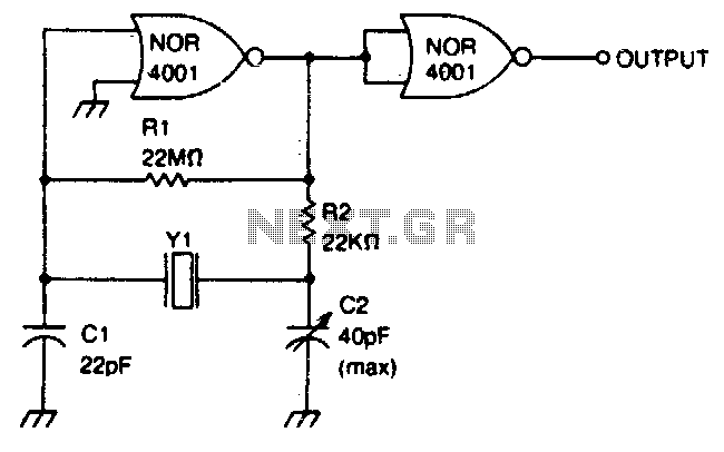
This circuit operates within a frequency range of 0 MHz to 2 MHz. The frequency can be finely adjusted to a specific value using the trimmer capacitor C2. Additionally, the second NOR gate functions as an output buffer. The circuit...
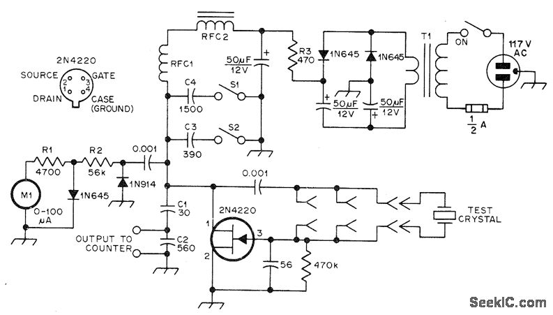
The JFET Pierce oscillator is designed to test any crystal within a frequency range of 50 kHz to 25 MHz, accommodating the upper frequency limit of fundamental-mode crystals without the need for tuning. It is capable of driving a...
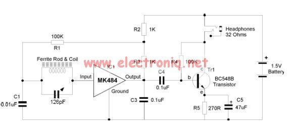
The MK484 AM radio circuit offers a comprehensive solution that includes an RF amplifier, detection, and automatic gain control (AGC) circuit. It requires only a few external components to achieve a high-quality AM tuner. The circuit features an input...