
Current leakage protection circuit

Current leakage protection devices are essential components in electrical safety systems, designed to prevent electric shock and equipment damage due to leakage currents. These devices utilize two primary technologies: electromagnetic and electronic. The electromagnetic type relies on a zero-sequence current transformer (TA) to detect current imbalances, while the electronic type enhances sensitivity and performance through advanced signal processing.
The zero-sequence current transformer operates by measuring the sum of the currents in a three-phase system. Under normal conditions, the primary current vector is zero, leading to no output from the transformer. However, when a leakage current occurs, it generates a secondary current that induces an electromotive force in the transformer's secondary coil. This induced voltage generates a trigger pulse that activates the thyristor (VTH), which is responsible for controlling the power disconnect mechanism.
The electronic circuit within the electronic leakage protection device amplifies the detected signal and compares it against predefined thresholds. If the leakage current exceeds the threshold, the thyristor is triggered, allowing current to flow through the trip coil (L). The trip coil energizes the automatic circuit breaker, which disconnects the load from the power supply. This process is crucial for ensuring user safety and protecting sensitive equipment from damage due to electrical faults.
Furthermore, the circuit includes a test feature, allowing users to verify the functionality of the leakage protection system. The test button (SB) connects a resistor (Ri) across the TA inputs and outputs, simulating a ground fault current. This test ensures that the leakage protection mechanism operates correctly and provides assurance of the device's reliability.
Overall, the design of current leakage protection devices incorporates robust components and advanced electronic circuitry to enhance performance, reliability, and safety in electrical systems.Current leakage protection is currently the most used and best leakage protection device. Current leakage protector fork into electromagnetic and electronic two, two leakage pr otection zero sequence current transformer are used as the detection element, the use of electromagnetic leakage protection leakage tripping release as a judgment element. Automatic circuit breaker as the actuator. Electromagnetic leakage protection than the sensitivity of the electronic differential, generally limited to 30mA, vibration resistance is also poor, but the ability to withstand voltage and lightning withstand strong electric shocks, by the power supply voltage, ambient temperature was less affected.
Electronic electric mattress protector is to be improved on the basis of electromagnetic leakage protection, based on the zero-sequence current transformer to detect weak leak telecommunications number after amplification by an electronic circuit, compare, and other plastic processing, electronic amplifying bribe trigger trip mechanism, then drive automatic circuit breakers disconnect the power. Woe to higher electronic electrical protection sensitivity, resistance to mechanical impact ability, but poor impact resistance to lightning, power supply voltage and its environmental performance are to a certain extent.
Electronic single-phase current-leakage protection circuit shown in Figure 14-5 Typical. When there is no electrical current Zhan, zero-sequence current transformer TA primary current vector is zero, TA non-inductive current output, the thyristor VTH is not turned on, the trip does not act, the normal power supply to the load. When the leakage current occurs, TA - secondary current vector and is no longer zero. TA secondary coil to generate induced electromotive force, the electromotive force induced by the formation of trigger pulse trigger circuit voltage, the thyristor conduction VTH.
AC 220V power supply voltage via the trip coil L, UR bridge rectifier, thyristor VTH anode, a cathode circuit coil L is energized to drive the leakage protection switch Qs action on the cut off the power, which played a Protective effect of preventing electric shock, reducing the chance of damage to the equipment. RV domain compressive resistance over voltage protection effect; SB button to test it and test circuit composed of the resistor Ri, both ends of the test circuit when connected to the conductor TA inputs and outputs of different phases, in order to press the SB, in TA flowing through a simulated ground fault current, check the leakage protection is normal.
Related Circuits
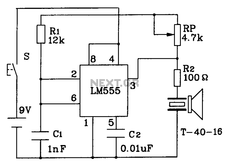
The circuit described is a 555 ultrasonic transmitter constructed to emit ultrasonic signals at a frequency of 40 kHz. It operates by generating oscillating pulse outputs from a 555 timer (specifically the T-40-16 model). The circuit is designed to...
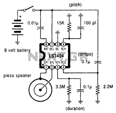
A high-quality melody circuit produces a slow decay waveform that generates chime-like notes. The pitch, tempo, and duration of the notes are all adjustable. The melody circuit is designed to offer a versatile sound generation capability, making it suitable for various...
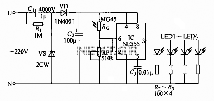
A 220V AC input is converted to a DC operating voltage of approximately 3.3V using a capacitive G buck regulator, a rectifier diode (VD), and a filter capacitor connected to an NE555 integrated circuit (IC). The IC functions as...
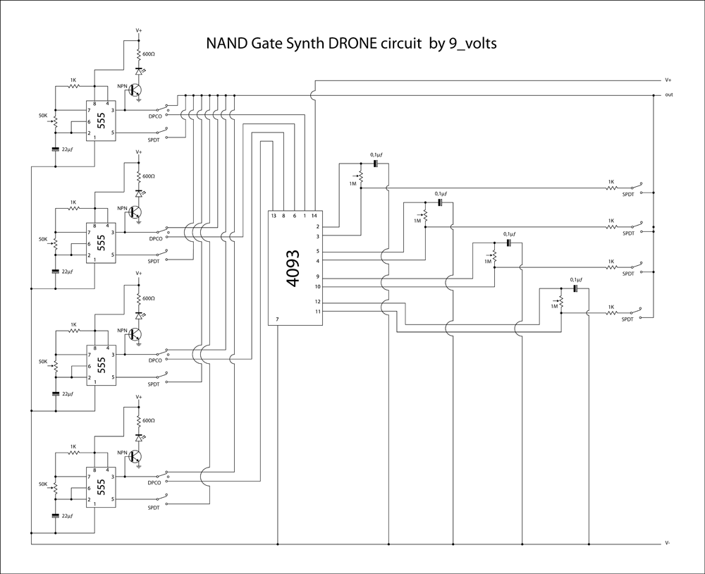
This is a brief jam session to explore the capabilities of a recently completed step sequencer. This device is quite enjoyable and expands creative possibilities. A detailed post with the circuit and instructions for building it will be provided...
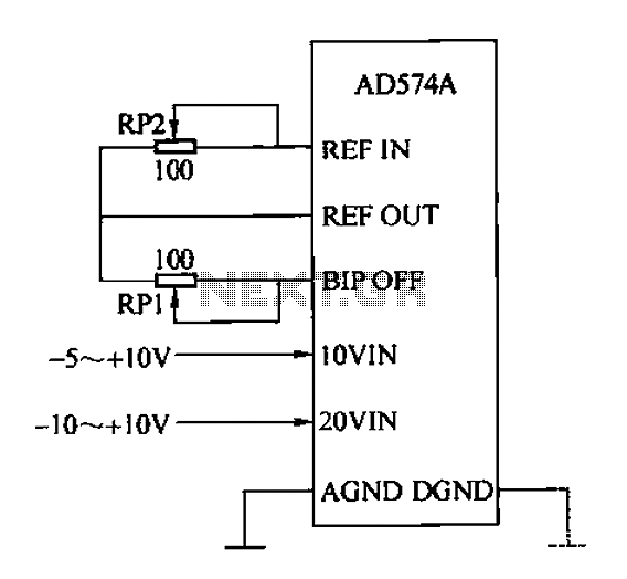
The AD574A is a high-performance 12-bit successive approximation analog-to-digital (A/D) converter that can interface directly with an 8 or 16-bit microprocessor bus. The input to the AD574A can be either unipolar or bipolar. The unipolar analog input voltage range...
This circuit will detect AC line currents of about 250 mA or more without making any electrical connections to the line. Current is detected by passing one of the AC lines through an inductive pickup (L1) made with a...