
Current Limiting Power Supply

This circuit description pertains to a power supply unit equipped with adjustable current limiting features. The switch SW3 serves a dual function as both an on/off switch and a selector for the mode of operation, either with a current limit or without. This flexibility allows users to choose between a regulated output where current is restricted to a predetermined level and an unrestricted output where the load can draw as much current as required, potentially leading to overcurrent situations.
The second switch, SW2, is integral to setting the current limit, providing three distinct options determined by the resistors R4, R5, and R6. These resistors are configured to establish current limits of 10mA, 25mA, and 65mA, respectively. Each resistor can be replaced or adjusted to customize the current limits according to the specific requirements of the application. This feature allows for flexibility in the design of the circuit, accommodating various load conditions.
The operation of the circuit is safeguarded by a feedback mechanism that monitors the output current. If the load attempts to draw more current than the selected limit, the output voltage will decrease, thereby protecting the circuit and the connected load from damage due to excessive current. This voltage drop is indicative of the current limiting action and can be monitored using a voltmeter connected to the output. The voltmeter serves as a visual indicator, alerting the user when the load exceeds the permissible current threshold, thus ensuring safe operation of the circuit under varying load conditions.
Overall, this design highlights the importance of current limiting in power supply circuits, providing both safety and flexibility for various electronic applications.SW3 is the on/off switch. It also lets you choose between the output with the current limit and the one without. SW2 provides a selection of three different limits. You can increase or decrease this number if you wish. The limits are fixed by R4, R5 & R6. They are set at 10mA, 25mA & 65mA respectively; but you can choose whatever limits you like. If you try to draw a current above the limit you`ve selected, the output voltage will fall. Thus, the voltmeter indicates when the load on the output is excessive. 🔗 External reference
Related Circuits
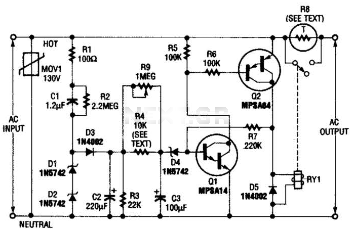
Q1 is an NPN Darlington transistor, and Q2 is a PNP Darlington transistor. MOV1 is a metal-oxide varistor, while R8 is a thermistor used for limiting inrush current. This circuit is designed to limit AC line current to a...
On average, how often do you need to call family members each day to inform them that dinner is ready or that it's time to leave? Typically, the person being called is in a different room, such as a...
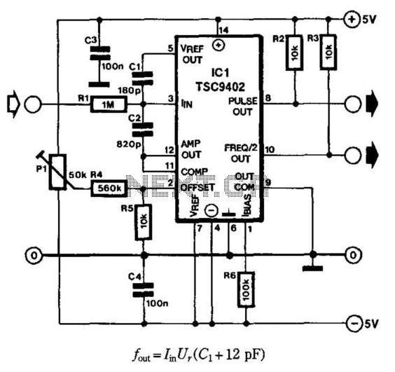
Teledyne Semiconductor's Type TSC9402 IC is highly suitable as an economical current-to-frequency converter. The maximum input current for the design depicted in the diagram is 10 mA (input voltage range is 10 mV to 10 V), while the output...
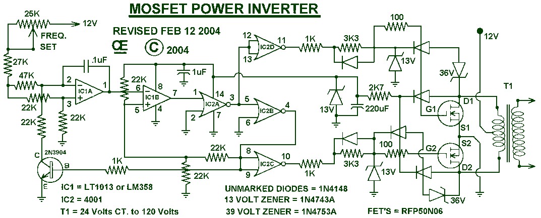
1000W Power Inverter circuit diagram: This is a power inverter circuit based on the MOSFET RFP50N06. The inverter is capable of handling loads up to 1000W, depending on the specifications of the transformer used. The RFP50N06 MOSFETs are rated...
This class-D audio amplifier is suitable for TV and home stereo systems. The TDA7882 integrated circuit (IC) provides a class-D audio amplifier solution. Since this IC has a single channel output, two units are required for stereo applications. The...
48 V phantom powering has become the standard for professional condenser microphones. The supply (or rather bias) voltage is applied over both wires of the microphone cable. Phantom power is a method used to provide power to condenser microphones through...