
Current Loop Light Level Detector

This two-wire light level detector circuit operates by using a single pair of wires for both power and signal transmission, which simplifies installation and reduces wiring complexity. The design typically employs a photodetector, such as a photodiode or phototransistor, to sense ambient light levels. When the light intensity changes, the photodetector generates a corresponding change in current.
The current loop configuration is often based on the 4-20 mA standard, which is widely used in industrial applications for transmitting analog signals over long distances. In this setup, the light level detected by the sensor modulates the current flowing through the loop. A higher light intensity results in an increased current, while lower light levels correspond to reduced current flow. This allows for precise monitoring of light levels in various environments.
The circuit may also include a signal conditioning stage to filter and amplify the output from the photodetector, ensuring that the signal is suitable for further processing or display. Components such as operational amplifiers can be used to improve the signal-to-noise ratio, providing a more accurate representation of the light level.
In addition, the circuit can be designed with adjustable thresholds to trigger alarms or activate other devices based on specific light level conditions. This feature enhances the versatility of the light level detector, making it suitable for applications ranging from automatic lighting control to environmental monitoring systems. Overall, the two-wire configuration, combined with the current loop principle, provides an efficient and effective solution for light level detection.This circuit is two wire light level detector, we don`t separate wires for power this sensor system and for delivering the output signal. With current loop, we. 🔗 External reference
Related Circuits
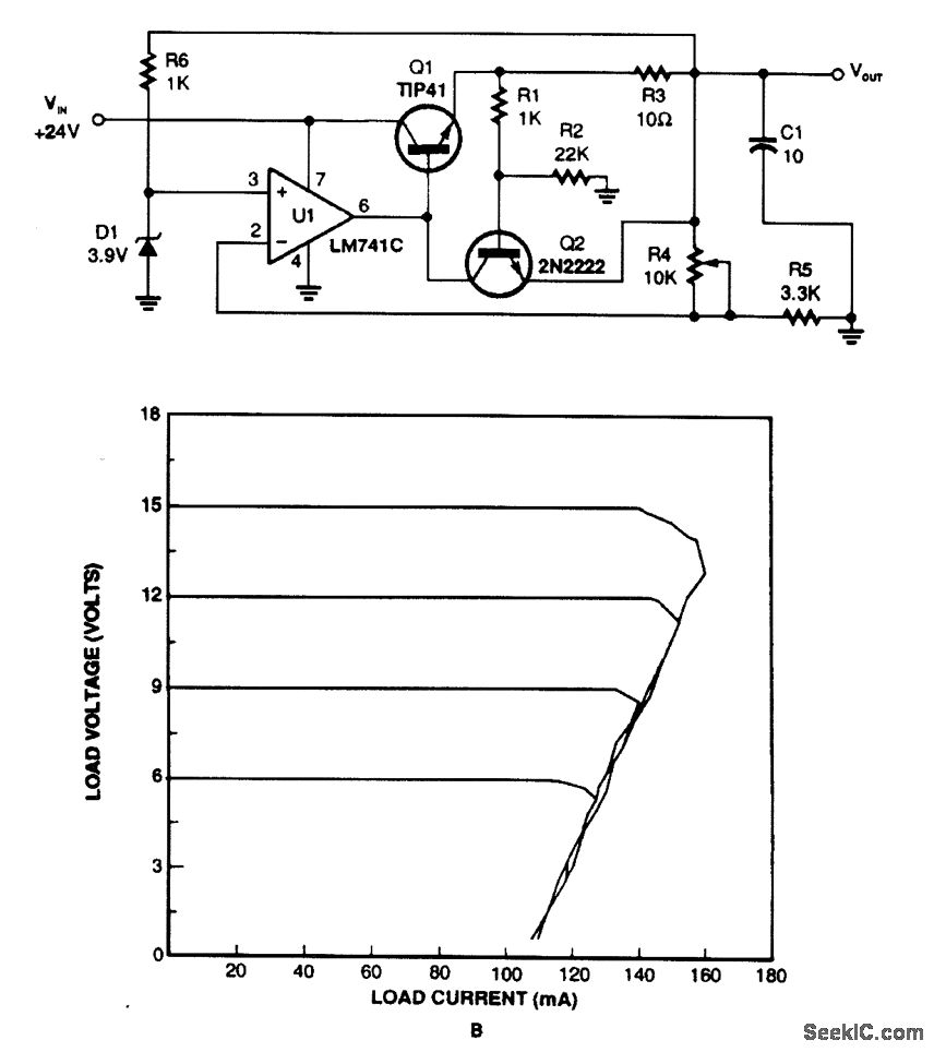
This regulator utilizes the voltage drop across resistor R3 to monitor current draw. When the current exceeds a certain threshold, Q2 is activated, which in turn disables Q1 and reduces the output voltage. Current limiting takes place when Q2...
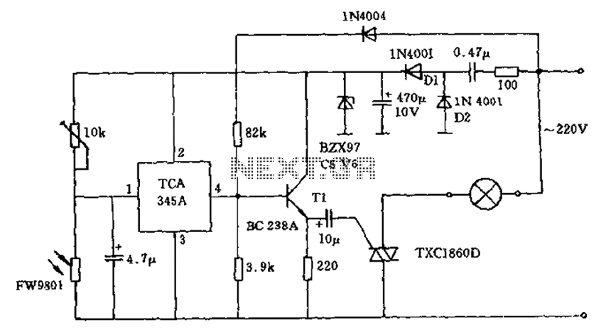
A 200W lamp switch control operates at a power supply voltage of 220V. It automatically turns the light on or off based on ambient illumination levels, specifically activating at approximately 100 lux. In low light conditions, a time-sensitive resistor...
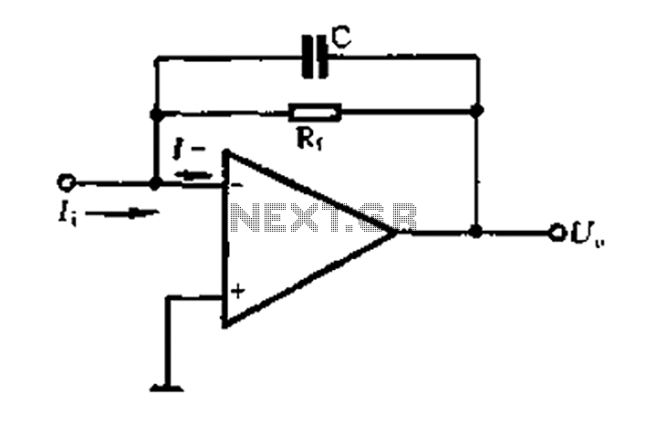
A current-voltage conversion circuit. A current-voltage conversion circuit is designed to transform an input current signal into a corresponding voltage signal. This type of circuit is fundamental in various applications, including sensor interfacing, signal conditioning, and analog-to-digital conversion processes. Typically,...
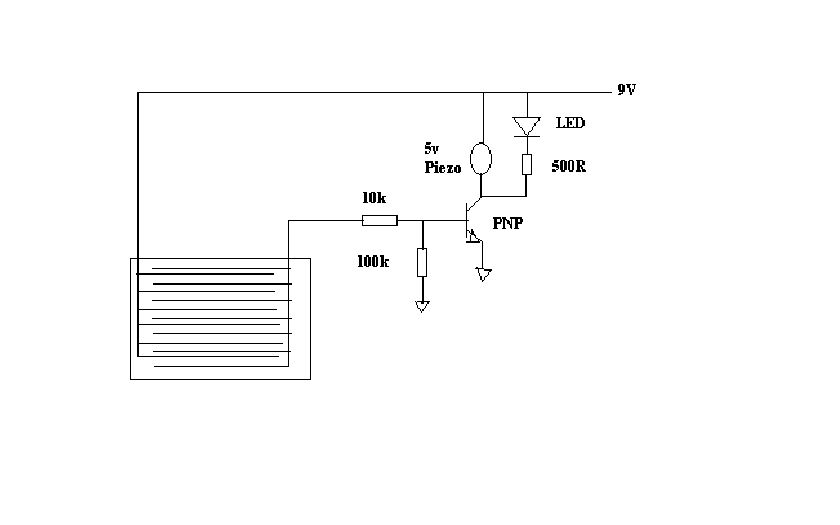
This project outlines a simple water detector circuit. The components required for this project include the following: 1. One IC 555 timer, and 2. A small-sized general-purpose relay. The water detector circuit utilizes the IC 555 timer configured in a...
This circuit provides automatic current limiting up to 8.4 A. Unlike current limiters that use only a resistor, this current limiting circuit does not drop the voltage significantly or keeps the voltage drop to a minimum until a specific...
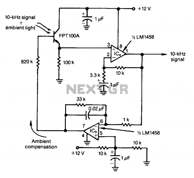
The feedback control of the phototransistor in this optical detector helps negate the effects of varying ambient light sources. The output of a modulated visible-light LED is detected, amplified, buffered, and fed through a low-pass filter. Ambient light signals...