
Data logging with an EEPROM

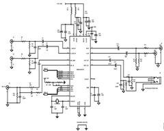
The circuit design integrates a PIC microcontroller, specifically the 18F4520, with an external EEPROM (24FC1025) for data logging purposes. The microcontroller is programmed to read analog signals from a designated input pin (AN0) through an ISR, which is triggered by a timer or an external event. The ISR reads the analog value, converts it as necessary, and writes the data to the EEPROM using I2C communication protocol.
The I2C bus is configured with the serial data line (SDA) connected to pin RC4 and the serial clock line (SCL) connected to pin RC3 of the PIC. The EEPROM requires specific pin configurations: A0, A1 are grounded, A2 is set high for normal operation, Vss is connected to ground, and Vcc is supplied with a high voltage to power the chip. The write-protect pin (WP) is grounded to allow for data rewriting.
For data transmission to MATLAB, an RS-232 interface is established with the PIC. The TX pin (RC6) and RX pin (RC7) are connected to the appropriate serial port on the PC, ensuring proper communication for data retrieval. The MATLAB script is designed to listen for incoming data and plot it accordingly.
The data logging operation is initiated by pressing the first button, which triggers the PIC to start collecting data points. Upon pressing the second button, the PIC waits for a response from MATLAB before transmitting the stored data from the EEPROM. The code includes a function for writing to the EEPROM, ensuring that the data is correctly formatted and stored.
Overall, the system is designed to efficiently handle the logging, storage, and communication of analog data, providing a robust solution for data acquisition and analysis in an embedded environment. The successful implementation allows for real-time data monitoring and subsequent analysis using MATLAB, enhancing the capabilities of the PIC microcontroller in practical applications.Your task is to use the PIC to log data from an analog input on an EEPROM, and after the data collection is over, to send the data back from the EEPROM to a PC running matlab. Use an interrupt service routine to read an analog input and write the value to an external EEPROM using I2C.
After reading in a fixed number of samples, perhaps 1, 000 or 10 , 000, the program should send the data back to a matlab program via an RS-232 link. The logged data should then be plotted by matlab. You should decrease the sample time until the ISR does not successfully complete. What is the fastest rate at which an analog input can be read and stored to the external EEPROM Try this for an analog input configured for both 8-bit (1 byte of data stored on the EEPROM) and 10-bit (2 bytes of data stored on the EEPROM). How much data can you store on the EEPROM An external EEPROM is useful when trying to store data. In addition to storing much more data than is available on the 18F4520 PIC, an EEPROM stores the data even when power is removed and can then be collected at a later time.
Storing large amounts of data over time is especially beneficial once communication can be made between the PIC and Matlab. Using the serial function in Matlab, the data can be obtained and then analyzed. In this project, we used the PIC to log data from an analog input onto an EEPROM and then later sent the data back from the EEPROM to Matlab to plot.
For our lab, we worked with a 24FC1025 EEPROM whose data sheet can be found here. Additionally, we established serial port connection between the PIC microcontroller and Matlab using the RS232. Our project also made use of two buttons. The first button tells the PIC to begin collecting data points from the analog input and storing the data onto the EEPROM.
The second button tells the PIC to send the data from the EEPROM to Matlab. To operate the EEPROM, PIN1 and PIN2, A0 and A1 are set to ground. PIN3, A2 is connected to high for normal operation. PIN4, Vss is used to ground the chip. PIN5, SDA is the serial data line and is connected to RC4 (PIN23) on the PIC. PIN6, SCL is the serial clock line which is connected to RC3 (PIN18) on the PIC. PIN7, WP is the write protect line. For our purposes, we set PIN7 to ground to disable this function and allow us to rewrite our data onto the EEPROM. PIN8, Vcc is connected to high to power the chip. In order to connect our PIC to Matlab, we use the RS232. As mentioned here, we connect the black wire to ground, the orange wire to pin 26, RC7 and the yellow wire to pin 25, RC6.
This project consists of two sets of code: code that is downloaded to the PIC to collect and store data to and send data from the EEPROM, and code that is used by Matlab to collect and plot the data. Within our code, we use a delay time of 5 msec since this is the time required to write the data to the EEPROM.
We collect 1000 data points in our code. However, the maximum number of data points is 128, 000 assuming each data point is a byte. The EEPROM is capable of storing 1024K bits or 128K bytes. /* superawesomeeepromcode. c Brandon Robins, Neil Tiwari, Jenny Yong 2009-2-11 Upon pressing button 1, take 1000 data values from AN0 and save to EEPROM Upon pressing button 2, wait for Matlab response, then output all data points from EEPROM */ #include <18f4520. h> #fuses HS, NOLVP, NOWDT, NOPROTECT #use delay(clock=40000000) #use i2c(MASTER, FAST, SCL=PIN_C3, SDA=PIN_C4, FORCE_HW) // use hardware i2c controller #use rs232(baud=9600, UART1) // Set up PIC UART on RC6 (tx) and RC7 (rx) #define EEPROM_WR 0xA0 // Define initial EEPROM write address block (See EEPROM data sheet) #define EEPROM_RD 0xA1 // Define initial EEPROM read address block (See EEPROM data sheet) int button1, button2, data_rx = 48; // Initialize variables int16 i, temp, value, address = 0, data; void seq_write(int16 address, int16 data)//Writing to the EEPROM function { i2c_start(); i2c_w
🔗 External reference
Related Circuits
A design example for a portable data acquisition system is provided, which significantly simplifies the circuit design task. The portable data acquisition system is designed to capture, process, and store data from various sensors and input devices. This system typically...
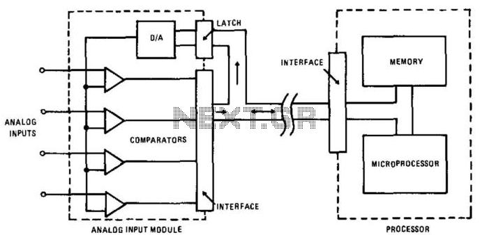
In this circuit, an HA-4900 series comparator is utilized alongside a digital-to-analog (D/A) converter to create a versatile, multichannel analog input for a data acquisition system. The processor first transmits an address to the D/A converter, after which it...
The IQ_Demod project demonstrates the application of the IQ_Demod_Setup and IQ_Demod_Data components within the ADS environment. These components are included in the ADS behavioral model suite, located under the System - Data Models palette. The file "IQ_demod_ckt.dsn" represents the...
A typical circuit for applications such as mobile phones, MP3 players, and portable electronics utilizing the SSM2602 Low Power Audio Codec is provided in the SSM2602 Applications Circuit Schematic. The SSM2602 Low Power Audio Codec is designed for high-performance audio...
Datagoo is based on the ATMEGA328P microcontroller, widely used by hobbyists in various Arduino projects. It can be programmed via any computer with a USB port when paired with an FTDI FT232RL USB-Serial circuit. Cost-effectiveness and simplicity were prioritized...

In the project, the LCD data ports are connected to port 1 of the controller, while the control pins, namely RS, E, and R/W, are connected to pins 3, 5, 6, and 2, 1 of the controller. The LCD...