
DC-10Mhz Amplifier for Oscilloscope

The described circuit is a dual-channel DC-10 MHz amplifier designed for use in an oscilloscope, providing a high-frequency response suitable for a variety of signal measurements. Each channel is identical, ensuring consistent performance across both inputs.
The key component of the amplifier is a field-effect transistor (FET) that serves as the input stage. For optimal frequency response, it is crucial that the FET is mounted directly on the adjustable attenuator switch. This arrangement minimizes parasitic capacitance and inductance that could degrade the signal quality, allowing for a more accurate amplification of high-frequency signals.
The vertical position pots, designated as R27 and R51, are utilized to adjust the DC level of the output traces on the oscilloscope display. These potentiometers do not influence the AC signal, ensuring that the amplification characteristics remain stable while allowing for visual adjustments of the waveform position on the screen.
It is important to note that this circuit does not incorporate a fine gain adjustment feature. The design is focused on providing a straightforward amplification process without the complexity of variable gain control, which can be beneficial in applications where simplicity and reliability are paramount.
The output voltage of the amplifier ranges from 0 to -15 volts, which is suitable for interfacing with standard oscilloscope inputs. This range provides ample headroom for various signal types while ensuring that the output remains within safe operating limits for connected devices.
For modern implementations of this circuit, it is advisable to consider utilizing contemporary operational amplifiers from reputable manufacturers such as Elantec, Harris, or Analog Devices. These components can offer improved performance characteristics, including higher bandwidth, lower noise figures, and better temperature stability, which can enhance the overall functionality of the oscilloscope input amplifier.The DC-10 MHz amplifier shown below is identical for both scope channels. The input FET should be mounted directly on the adjustable attenuator switch for best frequency response. The vertical position pots, R27 and R51, change the dc level of the traces, but do not affect the ac signal.
There is no fine (variable) gain adjustment in this circuit. The output voltage ranges from 0 to minus 15 volts. Modern op-amps from Elantec, Harris, or Analog Devices should be considered as a design alternative for the oscilloscope input amplifier shown on this page. 🔗 External reference
Related Circuits
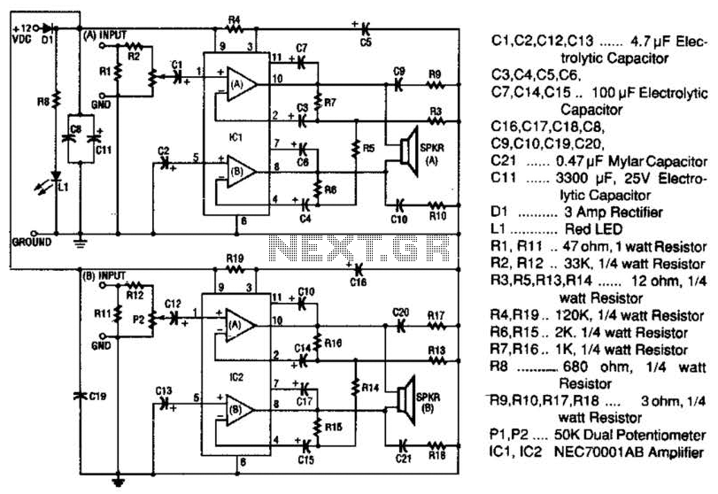
The 20-W + 20-W stereo amplifier consists of two complete, separate 20-W RMS bridge-type amplifiers. The input signal source is brought into the amplifier through a voltage divider network, which is composed of resistors R1, R2, and potentiometer P1....
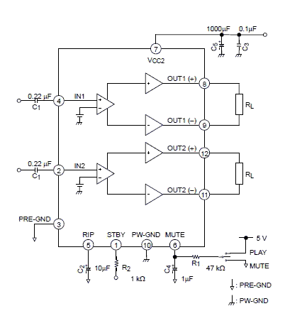
Using the TB2922HQ audio power IC can be designed a very simple and high efficiency power audio amplifier electronic project. TB2922HQ is 2ch BTL audio amplifier for TV or home audio applications. It includes and the pure complementary P-ch...
This circuit is mainly intended to provide common home stereo amplifiers with a microphone input. Using a stereo microphone the circuit must be doubled. In this case, two separate level controls are better than a dual-ganged stereo potentiometer. Low...
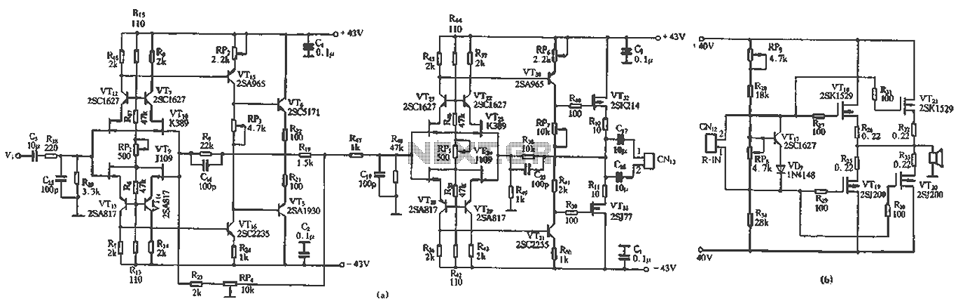
The circuit design features a unique technology and a reasonable structure utilizing all-discrete components with a Class A FET output. The complete circuit includes an input stage, an output stage, and a power level circuit to enhance performance, along...
This circuit illustrates a Car Radio Audio Amplifier using the TDA2003 integrated circuit. The datasheet for the TDA2003 includes electrical characteristics and schematic wiring details. The TDA2003 is a high-performance audio amplifier designed for automotive applications. It is capable of...
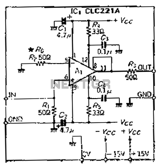
The CLC221A is designed with a traditional operational amplifier (OP) configuration. It is a high-performance current-feedback amplifier capable of operating in both non-inverting and inverting modes. The amplifier features a flat-rate characteristic, which is particularly effective when configured in...