
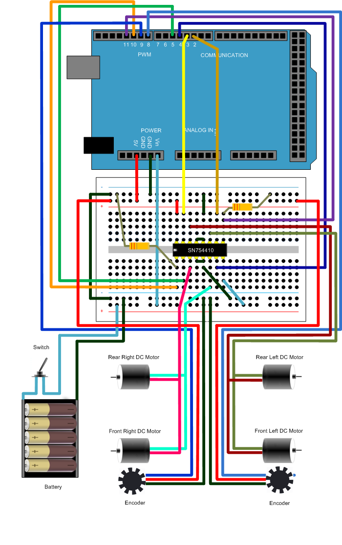
DC Motor Control

The DC motor control circuit is designed to provide precise control over the operation of a DC motor, enabling various functionalities such as forward rotation, reverse rotation, gradual slowing, and complete stopping. The circuit typically comprises a microcontroller unit (MCU) that interfaces with the motor driver, which is responsible for supplying the appropriate voltage and current to the motor based on the control signals received from the MCU.
The MCU can be programmed to execute specific control algorithms that determine the motor's behavior in response to user inputs or sensor feedback. For instance, pulse-width modulation (PWM) can be employed to regulate the speed of the motor by varying the duty cycle of the signals sent to the motor driver. This allows for smooth acceleration and deceleration, enhancing the overall performance of the motor control system.
The circuit may include additional components such as limit switches or encoders to provide feedback on the motor's position or speed, enabling closed-loop control. This feedback can be processed by the MCU to make real-time adjustments to the motor's operation, ensuring accurate positioning and speed control.
Power supply considerations are also crucial in the design of the circuit. The voltage and current ratings of the motor should be matched with the specifications of the motor driver and the power supply to prevent damage and ensure reliable operation.
In summary, this DC motor control circuit serves as a versatile solution for various applications requiring precise motor control, enabling functionalities such as co-rotation, rollback, slowing, and stopping, all managed efficiently by an MCU.Aboutthe DC motor control problem, This circuit is hoped to help those people who have the actual needs. This circuit`s corotation, rollback, slowing and stopping functions can be controlled by the connected MCU..
🔗 External reference
Related Circuits
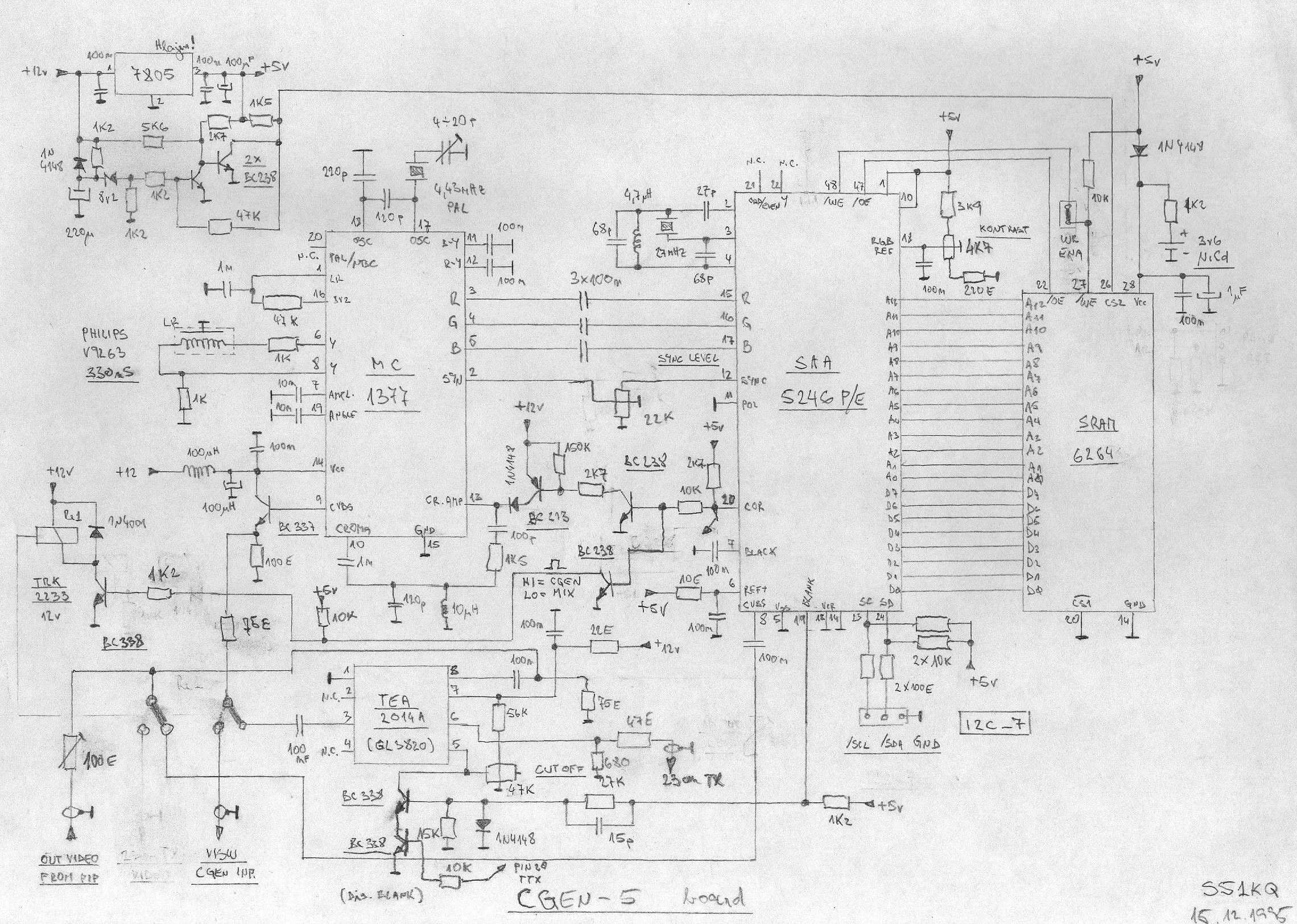
This is an image Schematic. No Description available. The provided input indicates that there is an image schematic without any accompanying description. In scenarios where a schematic is presented, it typically contains graphical representations of electronic components and their...
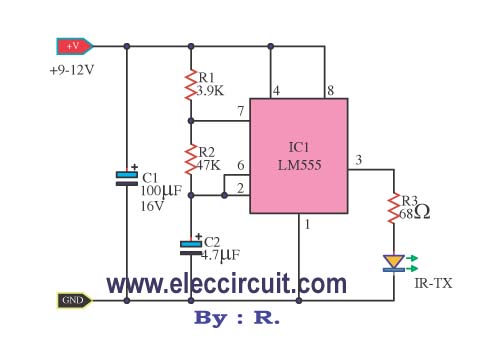
This infrared remote control transmitter circuit exhibits high performance and can be utilized with various infrared receiver circuits. It is designed for ease of construction and cost-effectiveness. Additionally, another circuit is intended for broader applications and requires programming to...
This document presents the circuit diagram of an IC-controlled emergency light with a charger, which functions as a 12V to 220V AC inverter circuit. The primary features of this circuit include automatic activation of the light during mains failure...
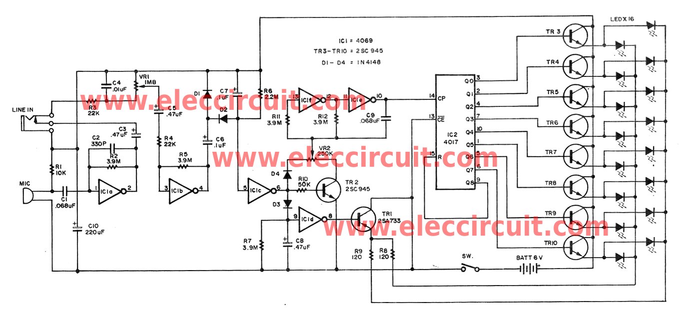
Individuals seeking a distinctive gift for Christmas and New Year may find this project appealing. Certification of this project will undoubtedly create a preference for it. The project in question appears to be a creative endeavor aimed at providing a...
File exchange, MATLAB Answers, newsgroup access, links, and blogs for the MATLAB and Simulink user community. The MATLAB and Simulink user community is supported through various platforms that facilitate knowledge sharing and collaboration among users. The File Exchange feature allows...
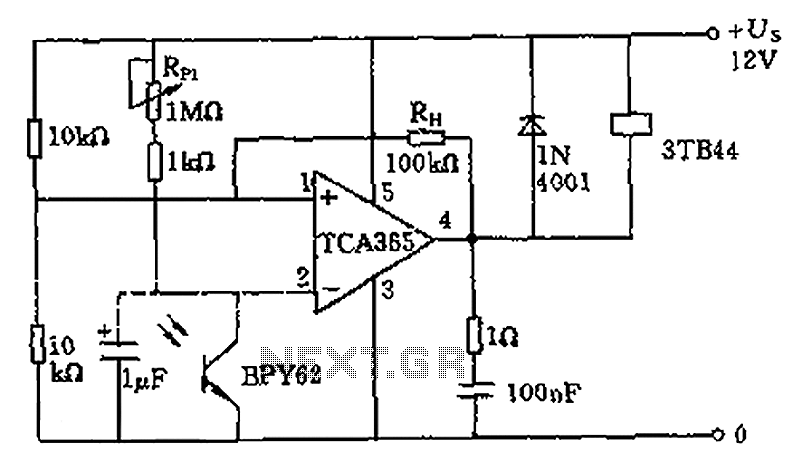
A bridge input circuit utilizing a phototransistor BPY62 and a power operational amplifier is capable of controlling power loads up to 8.5 kW. It features a voltage divider composed of two 10 kΩ resistors, creating a midpoint connection. The...