
DC RMS And Peak-to-Peak High Impedance Voltmeter

The integration of an active buffer circuit into an analog meter serves to improve its input impedance, which is crucial for accurate measurement in various electronic applications. A buffer circuit, often implemented using operational amplifiers (op-amps), isolates the meter from the circuit being tested. This isolation minimizes the loading effect that the meter might impose on the circuit, thereby preventing distortion of the measured signal.
In practical terms, an operational amplifier configured as a voltage follower can be used as an active buffer. The non-inverting input of the op-amp is connected to the signal source, while the output is connected to the analog meter. This configuration allows the op-amp to provide a high input impedance, typically in the range of megaohms, while maintaining a low output impedance. Consequently, the analog meter can accurately reflect the voltage of the source without drawing significant current from it.
The benefits of this approach are particularly evident in high-impedance applications, such as measuring signals from sensors or other sensitive devices. The active buffer circuit ensures that the analog meter can operate effectively without influencing the source signal, thus providing more reliable and precise readings. Additionally, the use of active buffering can enhance the frequency response of the measurement system, allowing for the detection of rapid signal changes that might otherwise be missed with a traditional analog meter.
In conclusion, incorporating an active buffer circuit into an analog meter design not only enhances its input impedance but also significantly improves measurement accuracy and reliability across a range of electronic applications.Analog meter normally doesn`t have high impedance since they don`t have buffer circuit inside. With active buffering, the input impedance of this circuit.. 🔗 External reference
Related Circuits

This car audio amplifier circuit is based on the LA47536 audio amplifier integrated circuit designed by Sanyo. This audio amplifier circuit is specifically designed for car audio power amplifiers. The LA47536 car audio amplifier IC features four output channels...
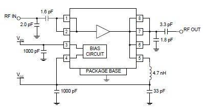
The RF2126 high-power linear amplifier IC, manufactured by RFMD, can be utilized to design a simple yet highly efficient amplifier for 2.45 GHz ISM applications, including WLAN and POS terminals. This component also serves as the final stage in...
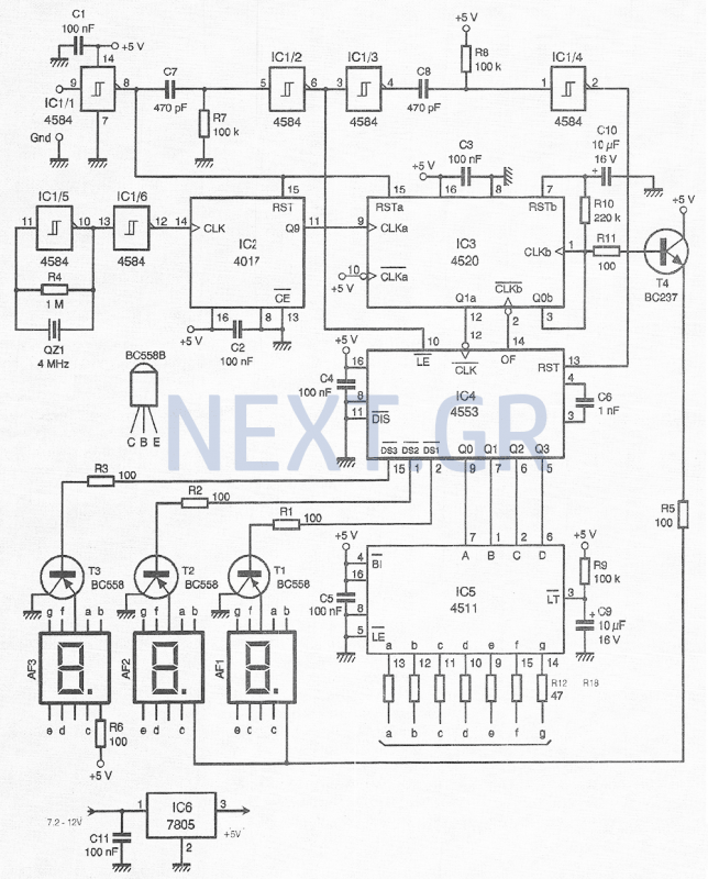
This compact device, designed primarily for modelers, provides instantaneous readings of pulse duration in milliseconds (ms). It can measure servomotor positions, typically ranging from 1 ms to 2 ms, and can also perform repetitive or non-pulsed measurements, such as...
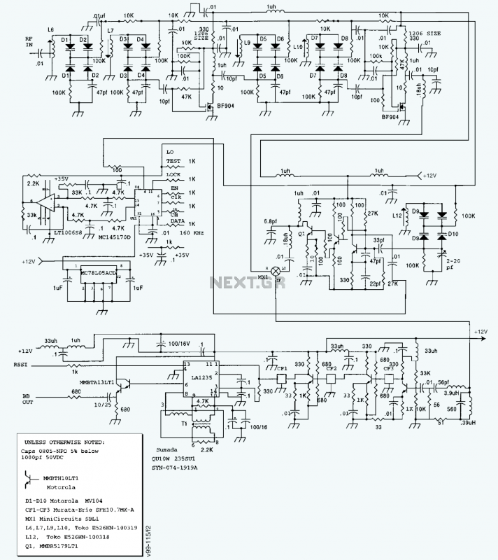
A block diagram and a schematic of the receiver are shown in Figures 2 and 3, respectively. In Figure 3, L6 and L7 are spaced 0.6 inch for a loss of about 0.5 dB. Q4 is the first RF...
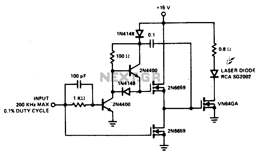
A faster driver can supply higher peak gate current to switch the VN64GA very quickly. The circuit uses a VMOS totem pole stage to drive the high power switch. The described circuit employs a high-speed driver to enhance the switching...
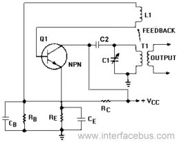
An Armstrong Oscillator is a type of oscillator that utilizes a tickler coil to provide feedback from the tank circuit. This oscillator generates a sine-wave output with constant amplitude and fairly constant frequency within the RF range. Inductor L1...