
Debounced Counter Made From Off-The-Shelf Chips

The SR latch is a fundamental bistable multivibrator circuit widely used in digital electronics for memory storage and state retention. The circuit typically consists of two cross-coupled NAND gates. The inputs to these gates are connected to the output of the other gate, creating a feedback loop that allows the circuit to maintain its last state until a new input is applied.
In practical applications, the SR latch can be used for debouncing mechanical switches, which are prone to noise and bouncing due to their physical contacts. The debounce circuit ensures that only clean transitions are registered, preventing erroneous counts in a connected counter or microcontroller. The design should include a double-throw switch that supports break-before-make operation, ensuring that only one input changes state at a time. This configuration allows the circuit to ignore transient states caused by bouncing.
When designing the debounce circuit, careful consideration must be given to the timing characteristics of the switch and the response time of the NAND gates. The propagation delay through the gates should be taken into account to ensure that the latch can respond quickly enough to valid input changes while filtering out noise.
In a microcontroller implementation, software debouncing can be employed alongside hardware solutions. The microcontroller can sample the input state at defined intervals, ignoring rapid changes within a specified debounce time. This hybrid approach can enhance reliability in environments with significant electrical noise.
In summary, the SR latch is an essential component in digital design, particularly for applications requiring stable state retention and noise immunity in switch transitions. The choice of switch type and circuit configuration directly influences the performance and reliability of the debounce mechanism.The real usefulness of the SR latch comes during input switch transitions. Let`s assume the input switch is a break-before-make and the switch starts in the up position. From the prior analysis, the inputs values when the switch is up are low, low, high, high, and the output is high. As the switch is toggled, it breaks the first input, changing it to high, low, high, high. Those values can be used to determine the output value. This means that even if the input switch signal bounces multiple times between low and high signals as it breaks the connection, the debounce output remains steady. Because the debounce output is steady, the counter doesn`t increment spuriously. Not surprisingly, the same steadiness occurs when the input switch starts in the down position and starts to break contact as it transitions up.
The output remains low. While this is exactly what we want, this also explains why a single-throw switch or pushbutton won`t work. This circuit keeps the output in a steady state when only one input is changing back and forth. Pushbuttons and single-throw switches only change one input. Double-throw switches provide more information. By requiring two inputs to change states, not just one, you can ignore all errors generated by either input at a given time.
You don`t care how long it takes for the errors (bouncing) to go away, but you`re ready to change states again right away if necessary. Software debouncing of pushbuttons relies on time as the second input. That is, the software assumes it takes a certain amount of time for the switch to settle down before more input can be reliably accepted.
This slows down the maximum switching rate and the software method is still vulnerable to long bounces. In the previous two examples, it was assumed that the switch is a break-before-make type of switch. Instead, if the switch is make-before-break type, the switch will output two low values into the SR latch.
A low input into a two-input NAND gates always results in a high output, regardless of the other input value into that gate. As such, it doesn`t matter what the prior state of the SR latch was, the make-before-break input switch will always result in the debounce circuit outputting high during input switch transitions.
This is undesirable behavior when toggling from the down position, as the bouncing will flip the input to the counter between low and high, causing extra counts. Therefore, the switch must be break-before-make double-throw, not make-before-break. Admittedly, this further reduces the occasions when the circuit may be useful to you. However, this is a limitation of using only two logic gates. In a microcontroller, you can write a slightly more complex algorithm that will work with either type of double-throw switch: There is one last pair of cases to consider that are classic for an SR latch.
If a break-before-make switch is in the center position (neither up nor down) during power up, what is the output From the prior analysis of the up and down transition states, we know that the SR latch will remain stable in its prior output state. If the individual NAND gate outputs happen to power up as either high, low or low, high , they will remain that way (because that`s identical to the already analyzed up/down transition states).
But what if the individual NAND gate outputs initially power up as high, high or low, low , feeding those value into the center inputs of the SR latch circuit Theoretically, the SR latch will repeatedly oscillate between a high output and a low output. In reality, the slight differences between transistors will cause one output to trip slightly sooner, causing the center inputs to no longer match each other, causing the circuit to stabilize.
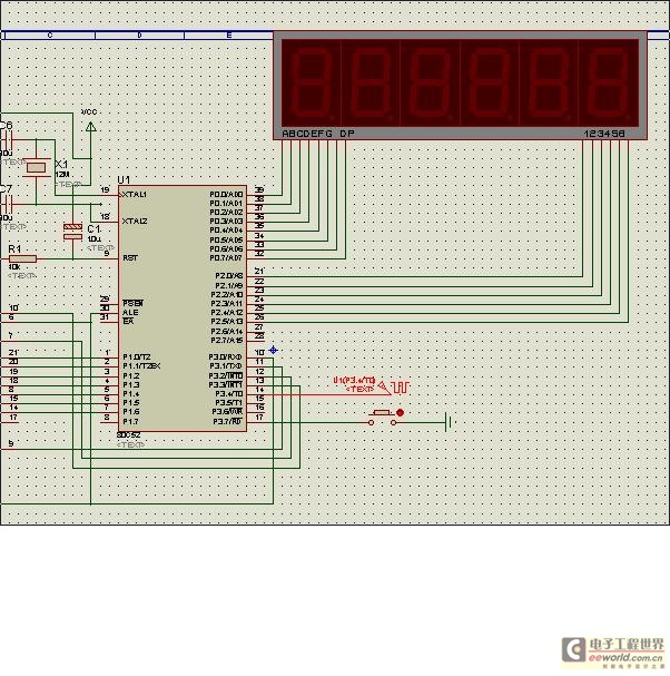
According to the first schematic in the book, after the input switch signal is debounced and pulled-up (if necessary), it is fed into a counter. Because the first schematic does not p 🔗 External reference
Related Circuits
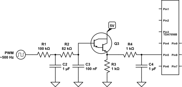
A voltage between 0.4 and 1.2 V is required on pin 5 to control the gain. In the initial two versions of the circuit, logic ICs and/or counters were utilized along with an operational amplifier and a resistor network...
If a negative supply is required for an operational amplifier or if a negative bias voltage is needed while operating from a single supply voltage, such as in battery applications. To generate a negative supply voltage from a single positive...
The standard circuit will display directly in Hz (1MHz max), and there is a separate on board divider that will allow you to display directly in KHz (approx 40MHz max). Because the display reads directly in Hz or KHz...
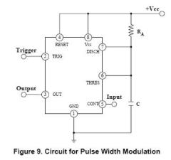
The circuit is effective for controlling the power supplied to devices such as fans, LEDs, or transformers and coils. By adjusting the pulse width, it is possible to control the speed of a fan without compromising torque. The IRF740...
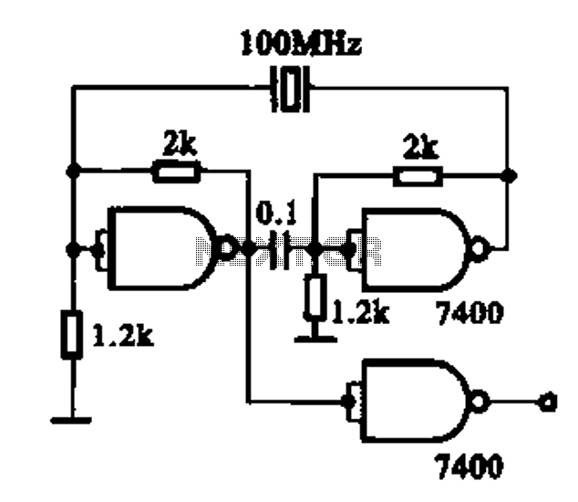
Crystal oscillator integrated circuits, specifically two diagrams of oscillator circuits with oscillation frequencies of 10 MHz and 20 MHz. Crystal oscillators are essential components in various electronic applications, providing stable frequency references for timing and synchronization purposes. The circuits presented...
This design synthesis considers the accuracy of frequency measurement and the requirements for response time. For instance, when measuring a frequency of 1 Hz, the measurement duration must exceed 1,000 seconds to accurately count the gate width. To ensure...