
Delayed ON LED

This circuit operates on the principle of a time delay using a capacitor and a resistor in combination with a transistor switch. Upon activation of the power supply, the capacitor C1 begins charging through the potentiometer R3. The charging time is determined by the RC time constant, which is the product of the resistance (R3) and the capacitance (C1).
As the capacitor charges, the voltage across it increases gradually. The transistor, which is configured in a common emitter mode, remains in the cutoff region until the voltage across the capacitor exceeds the base-emitter threshold voltage of the transistor. Once this threshold is surpassed, the transistor enters saturation, allowing current to flow through the LED, thus illuminating it.
The adjustable nature of R3 allows for fine-tuning of the delay period, making this circuit versatile for various applications requiring time delays. Increasing the resistance of R3 will extend the time it takes for the capacitor to charge to the necessary voltage, thereby increasing the delay before the LED turns on. Conversely, decreasing R3 will shorten the delay.
This simple LED delay circuit can be utilized in applications such as timers, alarms, or any device where a delayed activation is beneficial. The choice of capacitor value also plays a crucial role in determining the delay; larger capacitance will result in longer delays, while smaller capacitance will yield shorter delays.Here is very simple circuit in which the LED becomes ON only after a preset time the power supply is switched ON. When the power supply is switched on the transistor will be OFF. The capacitor now charges via the preset R3 and when the voltage across C1 is sufficient, the transistor switches ON and LED glows.
The ON delay depends on the value of P OT R3. You can increase the time delay by increasing the resistance of POT R3. 🔗 External reference
Related Circuits
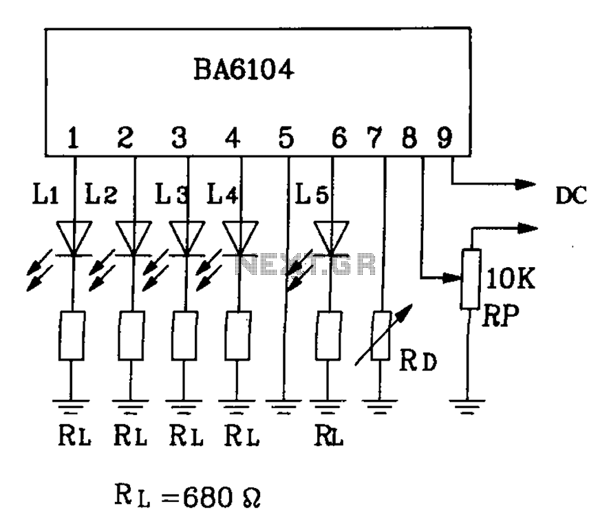
BA6104 is a five-digit LED level meter driver integrated circuit (IC) that features a basic application circuit. The input stage employs a PNP transistor with a composite base input, resulting in high input impedance. The output stage is configured...
This ultra-bright white LED lamp operates on 230V AC with low power consumption. It is suitable for illuminating VU meters, SWR meters, and similar applications. The cost of ultra-bright LEDs available in the market ranges from Rs 8 to...

This is a circuit using the LM3914 LED VU meter. It utilizes the LM3914 integrated circuit (IC1) along with a BC109C transistor. The circuit displays the level of audio signals (power music) in decibels (dB) across six levels using...
The bi-directional sequencer employs a 4-bit binary up/down counter (CD4516) along with two "1 of 8 line decoders" (74HC138 or 74HCT138) to create the well-known "Night Rider" display. A Schmitt Trigger oscillator generates the clock signal for the counter,...

This project I made for my little daughter. It is 24 channel light illumination. The schematic is very simple 24 LEDs, 1 MCU and some additional components. The main principle is dynamic indication, which is usually implemented for control...
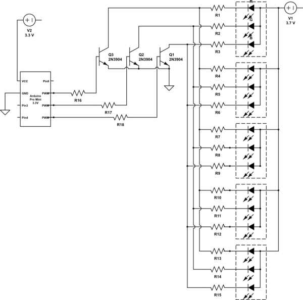
It is noted that the LEDs are not configured in parallel with the transistor. If they were, the LEDs would illuminate when the transistor is off. Instead, the LEDs are connected in parallel before entering the transistor. The transistor...