
Digital display circuit configuration

The common anode display circuit configuration consists of multiple light-emitting diodes (LEDs) connected in such a way that the anodes of all LEDs are connected to a positive voltage source. Each cathode is then connected to a control signal that determines whether the LED is turned on or off. This arrangement allows for a simplified control mechanism, as the common positive voltage can be maintained while individual LEDs are activated by grounding their respective cathodes.
In contrast, the common cathode display circuit configuration connects the cathodes of the LEDs to the ground, while the anodes are connected to a control signal that provides the positive voltage. In this setup, activating an LED requires applying a high signal to its anode, allowing current to flow from the anode to the cathode.
When designing these circuits, it is essential to consider the required current limiting resistors for each LED to prevent excessive current flow that could damage the components. The choice between a common anode and a common cathode configuration often depends on the specific application, the type of microcontroller or driving circuit used, and the desired control logic.
Both configurations can be effectively utilized in various applications, including seven-segment displays, alphanumeric displays, and other digital output devices, providing flexibility in design and implementation based on the project requirements.3 shows two kinds of digital display circuit, Total (a) adopt common anode circuit configuration, FIG. (B) the use of common cathode path structure.
Related Circuits
This circuit measures the distance covered during a walk. The hardware is housed in a small box that can be slipped into a pocket, and the display is designed as follows: the leftmost display D2 (the most significant digit)...
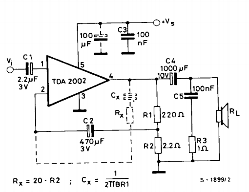
This is a power amplifier circuit built using the TDA2002 power amplifier IC module. It serves as a replacement for the original LM383, which is no longer available. The circuit is easy to assemble and requires a minimal number...

A simple frequency meter or frequency counter circuit featuring an LCD display and an AVR microcontroller. This includes a DIY schematic circuit diagram and embedded C code. The frequency meter circuit is designed to measure the frequency of input signals...
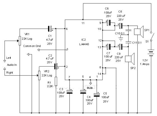
The LA4440 audio amplifier IC can be utilized to design a straightforward stereo power audio amplifier project, capable of delivering 6 watts of output power into an 8-ohm load. This audio amplifier IC features a minimal number of external...

There are important considerations when using additional memory, but it is certainly feasible. The MP3 player project utilizes 32 megabytes of memory. However, using more memory necessitates careful planning. The key factor is that the 8051 processor has a...
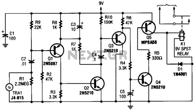
A GC Electronics P/N J4-815 transducer is utilized to receive 40-kHz acoustic remote-control signals. The receiver activates a relay to control another circuit. The GC Electronics P/N J4-815 transducer is designed specifically for the reception of 40-kHz acoustic signals, which...