
Digital Radar Speedometer

The Digital Radar Speedometer circuit operates by utilizing laser technology to provide accurate speed readings of moving objects. The laser LED emits a focused beam that travels toward the target vehicle, and upon striking the vehicle, the beam is reflected back to the radar's laser diode. The timing of the emitted and received signals is crucial for calculating the speed; the time taken for the signal to return is used to determine the distance traveled by the vehicle in that time frame. By applying the formula speed = distance/time, the circuit can compute the speed in kilometers per hour.
The choice of components, particularly the 74AS series logic chips, ensures that the radar can process signals with minimal latency, allowing for real-time speed measurement. The circuit design must include appropriate filtering and signal conditioning to handle the incoming signals from the laser diode effectively, ensuring that the measurements are stable and reliable.
The power supply design, utilizing a 9V battery, should include a voltage regulation circuit to maintain consistent performance even as the battery voltage decreases. The SPST switch allows the user to turn the device on and off, conserving battery life when the device is not in use.
In addition to the speed display, the overload LED serves as a critical indicator, providing visual feedback to the user when the detected speed exceeds the operational range of the device. This feature enhances the safety and usability of the radar speedometer, ensuring that users are aware of potential limitations in speed measurement.
The overall design of the Digital Radar Speedometer presents a compact and efficient solution for speed measurement, with a user-friendly interface and robust performance characteristics, making it suitable for various applications in automotive and traffic monitoring contexts.This circuit is a Digital Radar Speedometer. It allows us to evaluate the speed of any object moving, especially cars and other vehicles. The speed is calculated in kilometers per hour (KPH). Its display has three digits. This radar works with the laser reflexion. It sends laser radiation to the object and this object reflects the laser radiation to the radar. To evaluate the speed of a vehicle, we must be in front of it. In other words, the vehicle must come in our direction. The front of the radar must point the front of the vehicle. The radar has the shape of a pistol. In this radar, it has a laser LED and a laser diode. Both have a lens. The laser LED can send a spot of light to a distance of 90 m (295 ft). It`s very important that the distance range of the laser LED is 90 m, if not, the speed will not be calculated properly. The laser diode, which receives the light signal by the laser LED, must be able to detect the light which is same color as that emitted by the laser LED.
The laser diode and the laser LED must be placed one beside the other. They are protected by a tinted pane. They must be placed at the front of the radar and point the outside. The radar is powered by a 9V battery and it has a SPST switch to control its power state. The display, or the speed indicator, is placed at the rear of the radar, just on the right of the overload LED indicator. All the logic components of the circuit must be of the 74AS series and TTL type. Because they have short time of response (less than 1. 7 ns) and have high frequency supports (more than 200 MHz). The radar can evaluate the speed of an object moving between 0 to 999 km/h. After this speed, the overload LED indicator will turn on and the "999" will still displayed. The radar displays the speed during 3 seconds, after this time, it displays "zero" (0). 🔗 External reference
Related Circuits
The design of the digital logic probe centers around a pair of complementary bipolar transistors, which, in this application, are used as electronic switches. The digital logic probe is a diagnostic tool utilized for testing and analyzing digital circuits. The...

This circuit is based on the UM5100, which can record speech into digital memory and then play it back. The device is designed for use with static RAMs up to 256K bits or with EPROMs or ROMs for playback...
Unlike most surface-mounted device (SMD) resistors, SMD ceramic capacitors do not have their values marked. To determine the value of these capacitors, a capacitance meter is required. SMD ceramic capacitors are widely used in modern electronic circuits due to their...
A circuit utilizing a standard digital quartz electronic watch, with its crystal soldered, forms a digital frequency meter as illustrated by the connected circuit. The test signal is applied to the E and F sides via components such as...
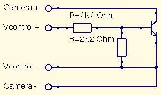
This is a straightforward guide to constructing a digital switch for a camera, enabling photo capture through microcontrollers. Required components include: 1. A digital switch for a camera can be implemented using a microcontroller, such as an Arduino or...
With this counter you can count laps for example (in conjunction with the Simple light trap). The circuit uses two TTL ICs 74LSxx the series. The left IC is a decimaalteller. The input pulses 14 are counted and converted...