
Digital Remote Thermometer Circuit With Receiver and Transmitter

This circuit operates based on a robust architecture designed for high accuracy in temperature measurement. The precision temperature sensor (IC1) is essential for translating temperature changes into a corresponding voltage signal. The linear output of IC1 ensures that the voltage change is directly proportional to temperature, which is crucial for maintaining measurement accuracy. The voltage-frequency converter (IC2) is responsible for converting the small voltage signals into frequency bursts, facilitating the transmission of data over the mains supply lines.
The use of transistors Q1 and Q2 in the circuit is critical for amplifying the frequency pulses to ensure that they can travel over long distances without significant loss. The inductors and capacitors (L1, C7, C8, C1, and C2) are strategically placed to filter and isolate the signal, preventing interference from other electrical noise present in the mains supply.
The counting mechanism is handled by IC5, which is synchronized with the time-base generator (IC4) to ensure accurate counting of the frequency bursts. The multiplexing technique employed allows for the efficient display of temperature readings on the three 7-segment displays, while the BCD-to-7 segment decoder (IC6) translates the binary-coded decimal outputs from IC5 into a format suitable for display.
Overall, this circuit exemplifies a well-designed system for precise temperature measurement and display, utilizing standard electronic components to achieve reliable performance over considerable distances.This circuit is intended for precision centigrade temperature measurement, with a transmitter section converting to frequency the sensor`s output voltage, which is proportional to the measured temperature. The output frequency bursts are conveyed into the mains supply cables. The receiver section counts the bursts coming from mains supply and show s the counting on three 7-segment LED displays. The least significant digit displays tenths of degree and then a 00. 0 to 99. 9 °C range is obtained. Transmitter-receiver distance can reach hundred meters, provided both units are connected to the mains supply within the control of the same light-meter. IC1 is a precision centigrade temperature sensor with a linear output of 10mV/ °C driving IC2, a voltage-frequency converter.
At its output pin (3), an input of 10mV is converted to 100Hz frequency pulses. Thus, for example, a temperature of 20 °C is converted by IC1 to 200mV and then by IC2 to 2KHz. Q1 is the driver of the power output transistor Q2, coupled to the mains supply by L1 and C7, C8. The frequency pulses coming from mains supply and safely insulated by C1, C2 & L1 are amplified by Q1; diodes D1 and D2 limiting peaks at its input. Pulses are filtered by C5, squared by IC1B, divided by 10 in IC2B and sent for the final count to the clock input of IC5.
IC4 is the time-base generator: it provides reset pulses for IC1B and IC5 and enables latches and gate-time of IC5 at 1Hz frequency. It is driven by a 5Hz square wave obtained from 50Hz mains frequency picked-up from T1 secondary, squared by IC1C and divided by 10 in IC2A.
IC5 drives the displays` cathodes via Q2, Q3 & Q4 at a multiplexing rate frequency fixed by C7. It drives also the 3 displays` paralleled anodes via the BCD-to-7 segment decoder IC6. Summing up, input pulses from mains supply at, say, 2KHz frequency, are divided by 10 and displayed as 20. 0 °C. 🔗 External reference
Related Circuits
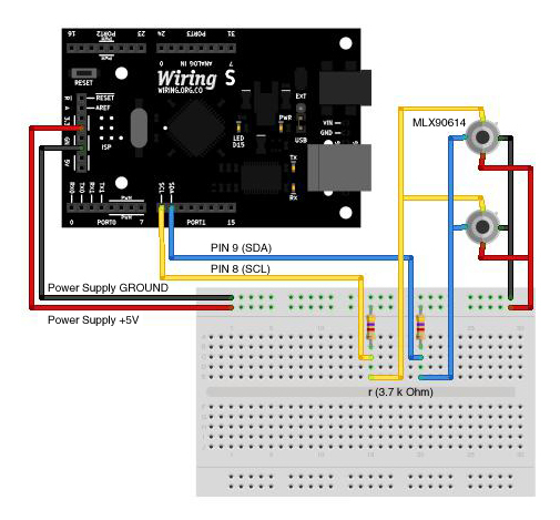
The MLX90614 is an infrared thermometer that allows for non-contact temperature measurement, providing average temperature readings for objects within its view range. Besides its primary function of measuring temperature, it can also be utilized for motion or presence detection....
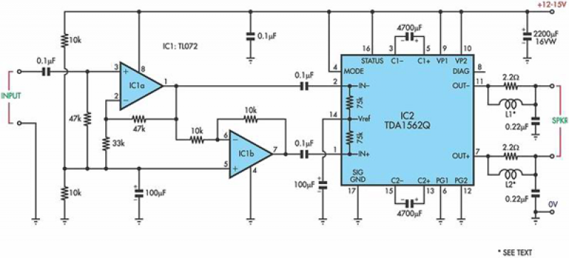
This circuit is based on a Philips class-H audio amplifier integrated circuit (IC) and can deliver 36W RMS or 70W music power, all from a 13.8V supply. The Mighty Midget Amplifier is capable of providing approximately 36W RMS continuous...
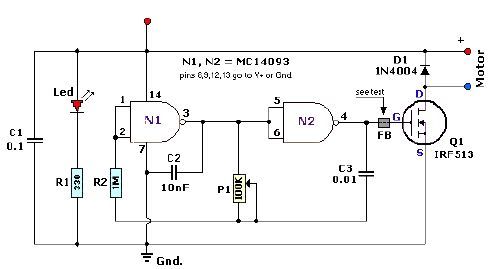
A quad 2-input NAND Schmitt trigger circuit can be designed using the MC14093 CMOS type IC, which serves as a simple pulse width modulation (PWM) controller electronic project. This PWM controller is straightforward and requires only a few external...
The LM317 is an adjustable, positive 3-terminal voltage regulator capable of supplying 100 mA (for RA87U control) or 1.5 A (for Order Code UF27E and N61CA) across an output voltage range of 1.2 V to 37 V. These voltage...
Designing an audio amplifier from scratch using discrete components is an engaging task, as it enables users to create amplifiers that meet diverse requirements. Audio amplifiers can enhance low-level sounds from mobile devices, making them louder and more vibrant....

The information apparatus includes a buck rectifier power supply providing Vdd at +12V, a timing circuit, a multivibrator, and the output from the first amplifier. The components R1, RP1, and C3 are used to initiate timing, with the timing...