
Digital Roulette with Display circuit

The digital roulette circuit operates by utilizing an oscillator (IC1) to generate a clock signal. This clock signal is fed into a counter (IC2), which counts the pulses from the oscillator. The output of the counter is then used to control a series of transistors (Q1-7), which in turn drive a common cathode display (DSP1). The display shows the current state of the roulette, typically representing numbers or symbols that simulate the spinning wheel of a roulette game.
The oscillator is crucial for providing the timing needed for the counter to function correctly. Depending on the design, the frequency of the oscillator can be adjusted to change the speed at which the numbers appear on the display, simulating the randomness of a roulette game. The counter IC2 is responsible for counting the pulses and determining which number or symbol should be displayed at any given moment.
Transistors Q1-7 serve as switches that control the segments of the common cathode display. Each transistor corresponds to a specific segment of the display, allowing for a visual representation of the counter's output. When a particular number is reached in the counting sequence, the corresponding transistors are activated, illuminating the appropriate segments of the display.
The circuit can be powered by a 9V battery for portability or connected to an external power supply for stationary use. This flexibility allows the circuit to be used in various applications, from personal entertainment to educational demonstrations of digital electronics principles.
In summary, this digital roulette circuit demonstrates fundamental electronic principles, including oscillation, counting, and display control, making it an excellent project for those interested in digital electronics and circuit design.This circuit is a small digital ?roulette``. It is constituted by oscillator IC1, the counter IC2, the transistors Q1-7 that drive the display common cathode DSP1. The supply basically becomes from a battery 9V, but can become also from one power supply.. 🔗 External reference
Related Circuits
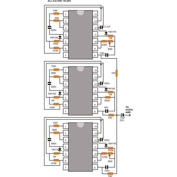
This document discusses a compact machine gun sound effect generator circuit. Once constructed, it can be integrated with any audio amplifier to create a realistic war-like simulation. This small hobby project is suitable for all electronics enthusiasts and generates...

A 1.2-kHz oscillator utilizing a potentiometer and steering diodes allows for a duty cycle adjustment ranging from 1% to 99%. The frequency can be altered by varying the capacitor CI. It is important to note that the diodes may...
A newer version of this circuit board is available. Rev 4 includes a faster CPU, more memory, more I/O, and an optional LCD. It is recommended to use Rev 4 for new projects. Although the older board is no...
The circuit element appears to be problematic, particularly with the Shu component. After a prolonged period following the activation of the start button, there are indications of unexpected behavior, such as the turtles producing sperm-like substances. The Pi Wen...
The text of the Arduino reference is licensed under a Creative Commons Attribution-ShareAlike 3.0 License. Code samples in the reference are released into the public domain. The Arduino platform is an open-source electronics prototyping environment that enables users to create...
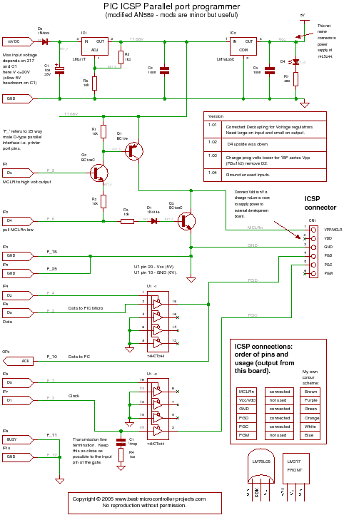
A PIC programmer circuit that operates using long cables from a PC to the programmer. The PIC programmer circuit is designed to facilitate the programming of PIC microcontrollers via a connection to a personal computer (PC) using extended cabling. This...