
Digital Thermometer

The digital thermometer circuit utilizes the PIC16F688 microcontroller as the main processing unit, interfacing with the DS1820 temperature sensor to accurately measure ambient temperature. The DS1820 operates over a wide temperature range, making it suitable for various applications, including monitoring environments that may experience extreme conditions. The microcontroller communicates with the sensor through the RA5 pin, retrieving temperature data in a 9-bit format.
The temperature data is processed within the PIC16F688, where it is read in two separate bytes: TempH (temperature high byte) and TempL (temperature low byte). These bytes are then combined to form a single 2-byte integer representing the temperature value. To facilitate conversion from Celsius to Fahrenheit without utilizing floating-point arithmetic, the temperature is multiplied by a factor of ten, allowing for straightforward integer calculations.
The processed temperature is then transmitted to a 16x2 LCD display using a 4-bit data transfer method, with data lines connected to ports RC0 through RC3. Control signals for the LCD, including Register Select (RS) and Enable (E), are managed via ports RC4 and RC5. The Read/Write pin of the LCD is grounded, indicating that this design does not require reading data from the display, simplifying the control logic.
A 10K potentiometer is incorporated into the circuit to adjust the LCD's contrast, ensuring optimal visibility of the displayed temperature readings. It is important to note that the DS1820 sensor should be isolated from the main circuit when measuring very low temperatures, such as those found in a freezer, to prevent damage to the LCD and other components. Instead, the sensor can be placed in the cold environment while connected to the main unit via three wires, maintaining functionality and accuracy.
In summary, this digital thermometer design effectively combines the capabilities of the PIC16F688 microcontroller and the DS1820 temperature sensor to provide reliable temperature readings in both Celsius and Fahrenheit, displayed conveniently on an LCD screen. The project illustrates important considerations for temperature measurement and component compatibility, particularly in varying environmental conditions.Room temperature plays a vital role in determining human thermal comfort. This digital thermometer is designed to measure room temperature and display it on a LCD screen in both Celsius and Fahrenheit scales. A PIC16F688 microchip is used as the main controller that reads temperature from DS1820, a 3-pin digital temperature sensor from Dallas semiconductors (now Maxim).
The sensor is designed to measure temperature ranging from -55 to +125 °C in 0.5 °C increments. The room temperature doesn't go that far but the firmware written for the PIC is able to read and display the entire temperature range of DS1820. I have tested it from -4.5°C (my freezer temperature) to 105.5 °C (by bringing a soldering iron tip close to the sensor). If you want to measure your freezer temperature too, don't put the entire unit inside it, as some of the components (like LCD) may not work at that low temperatures.
Rather put only the sensor inside the freeze and connect it to the rest of the system through three wires. For a better understanding of how DS1820 sensor works, I recommend to read the datasheet from Maxim website.
Remember that DS1820 and DS18B20 (both are temperature sensors) have architectural differences, and so DS18B20 will not work here. This project works with DS1820, and it would work with DS18S20 (later version of DS1820) too by changing the temperature conversion time in the firmware.
Read this to find the difference between DS1820 and DS18S20, http://www.maxim-ic.com/datasheet/index.mvp/id/3021 PIC16F688 reads data from DS1820 sensor through RA5 port, and the computed temperature is sent to the LCD through RC0-RC3 ports. It means the data transfer from PIC to LCD is achieved in 4-bit mode. The Register Select (RS) and Enable (E) signals for LCD are provided through ports RC4 and RC5. The Read/Write pin of the LCD is grounded as there is no data read from the LCD in this project. The contrast adjustment of LCD is done with the 10K potentiometer shown in the circuit diagram. The temperature reading from DS1820 is 9-bits which are read by PIC16F688 in two bytes (TempH and TempL), and then are combined into one 2-byte integer.
In order to avoid floating point math during C to F conversion, the temperature value is first multiplied by 10. For example, 24.5 C becomes 245. Now C to F conversion is fairly easy. 🔗 External reference
Related Circuits
This project Digital gated Emulator using Microcontroller is used to emulate the basic gates such us NOT, OR, AND. The system has the selector switch by which we can select any gate. The system has two inputs and one...
The receiver circuit and display module will receive the high-frequency AC power cord and decode it to provide actual temperature readings using digital IC No. CD4553 (Three-digit BCD Counter IC) and IC CD4511 (BCD-to-7-Segment Latch/Decoder/Driver IC). The frequency pulses...
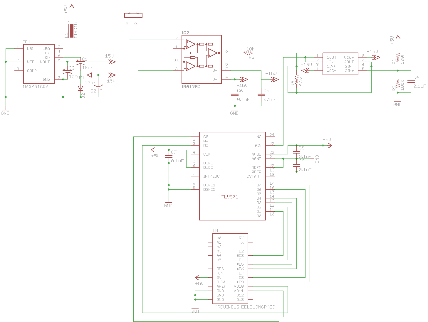
A digital oscilloscope is being developed using Arduino, designed as an Arduino Shield. The current implementation functions but exhibits signal distortions. A TLV571 chip is utilized in the design. The project involves creating a digital oscilloscope that can be mounted...
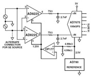
The Common Mode Rejection Ratio (CMRR) facilitates the rejection of high-frequency common-mode voltages, leading to the attenuation of elevated ambient noise levels from utility lines, industrial machinery, and other sources of radiation. The circuit diagram presented illustrates the advantages...
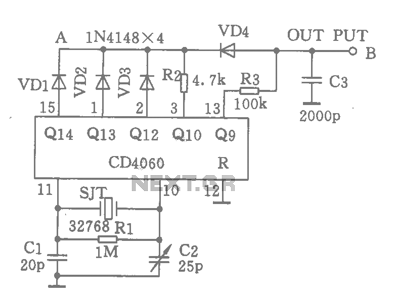
A CD4060 integrated circuit, combined with a 32,768 Hz crystal oscillator, is utilized to create a highly accurate clock source that generates 60 pulses per second. The operation is based on the division of the 32,768 Hz pulse output...
This document serves as a resource for developers who are new to Texas Instruments (TI) ARM-based processors, as well as for seasoned developers seeking to deepen their understanding of the different ARM architectures. It starts with an overview of...