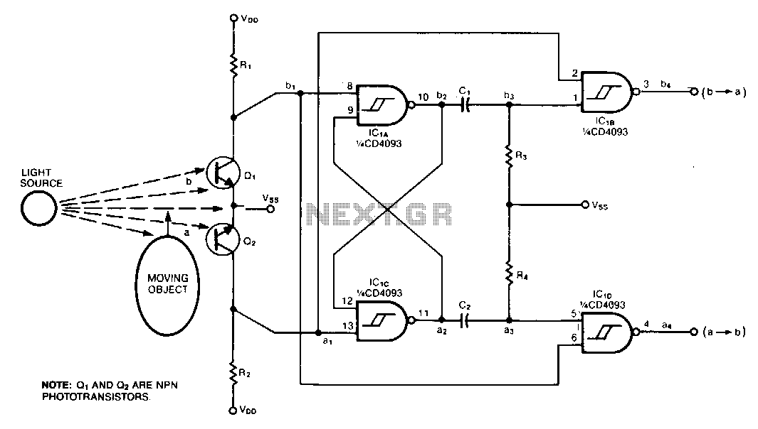
Direction-detector-decoder

This circuit was designed to monitor the traffic of bumblebees entering and exiting the hive, distinguishing between a-to-b motion and b-to-b motion. When paired with an optical decoder, the circuit differentiates between clockwise and counterclockwise rotation, providing a resolution of one output pulse per quadrature cycle. Q1 and Q2 are positioned so that a moving object first obstructs one phototransistor, then both, and finally the other. Depending on the direction of the object's movement, either IC1B or IC1D generates a negative pulse when the moving object blocks the second sensor. An object can reach condition 3 and retreat without triggering an output pulse, meaning the circuit disregards any probing or jittery movements. However, if an object reaches condition 4, a retreat will result in a pulse indicating the opposite direction. The time constants R3C1 and R4C2 define the output pulse width, with a 100 kΩ and 100 pF combination yielding 10 µs pulses. Select pullup resistors R1 and R2 from the 10 kΩ to 100 kΩ range based on the sensitivity required for the application.
The circuit operates on the principle of detecting motion through optical sensors, specifically using phototransistors that react to the interruption of light caused by a moving object, such as a bumblebee. The arrangement of Q1 and Q2 allows for the detection of the direction of movement by creating a sequence of light blockage. The output is generated through integrated circuits IC1B and IC1D, which are responsible for producing negative pulses based on the sensor inputs.
The design incorporates a mechanism to filter out irrelevant movements, ensuring that only significant motions—those that indicate a bumblebee entering or exiting the hive—are registered. This is crucial in environments where minor disturbances could lead to false readings. The circuit's ability to differentiate between various motion states is enhanced by the time constants set by R3C1 and R4C2, which determine how long the output pulse remains active. The choice of resistor values for R1 and R2 is critical; they must be selected carefully to match the sensitivity requirements of the specific monitoring application, ensuring that the circuit responds appropriately to the presence of bumblebees while minimizing noise from other movements.
Overall, this circuit serves as an effective tool for monitoring bumblebee activity, providing valuable data for research and ecological studies, while its design allows for flexibility in sensitivity and response time based on the user's needs.This circuit, which was developed to monitor the traffic of bumblebees in and out of the hive, differentiates a-to-b motion from b-to-b motion. When used with an optical decoder, the circuit distinguishes clockwise from counterclockwise rotation and provides a resolution of one output pulse per quadrature cycle.
Q1 and Q2 are mounted so that a moving object first blocks one phototransistor, then both, then the other. Depending on the direction in which the object is moving, either IC1B or IC1D emits a negative pulse when the moving object blocks the second sensor.
An object can get as far as condition 3 and retreat without producing an output pulse; that is, the circuit ignores any probing or jittery motion. If an object gets as far as condition 4, however, a retreat will produce an opposite-direction pulse.
The time constants R3C1 and R4C2 set the output pulse width. A 100 Kohm/lOOpF combination, for example, produces 10us pulses. Select a value for pullup resistors R1 and R2 from the 10 K to 100 K!l range, according to the sensitivity your application requires.