
Discrete Robot

The schematic of the described robot includes several key components: the light-dependent resistors (LDR1 and LDR2), which are strategically placed to detect light intensity from different directions; the window discriminator (TCA965), which processes the voltage levels from the LDRs and determines the robot's movement based on the light conditions; and the motor control transistors (T1 and T2) that activate the motors based on the outputs from the window discriminator. The voltage divider formed by R1, R2, and the LDRs allows the robot to establish a reference point for the light levels, enabling it to navigate effectively. The use of an IR sensor (Sharp IS471) for obstacle detection adds an additional layer of functionality, allowing the robot to respond dynamically to its environment. The flexibility of the design allows for various configurations and adaptations, enabling users to experiment with different components and layouts to achieve desired behaviors. The overall design emphasizes simplicity and adaptability, making it suitable for educational purposes and hobbyist projects.This simple robot, which responds to light and avoids obstacles, can be built without using a microcontroller, programmer or PC. The only special` component in the circuit is a window discriminator (a fancy version of a window comparator).
Resistors R1 and R2 in combination with light-dependent resistors LDR1 and LDR2 form a voltage divider (with the current being limited by R1 and R2 for bright light). Window discriminator TCA965 compares the mid-point voltage with an upper threshold value (adjustable using P1) and a lower threshold value (adjustable using P2). Outputs AU, AI, AO, and AA go High if the voltage lies below, inside, above or outside this window, respectively; otherwise they remain Low.
Output AA switches transistor T1, which drives the right-hand motor. The light-dependent resistors can be attached on the left and right sides of the vehicle, or at the front and rear. This causes the robot to turn to the right, due to the motor on one side being stopped, until the desired lighting relationship is restored.
The vehicle will then continue to travel in a straight line until the lighting relationship again changes, at which point it will again turn, and so on. You can experiment with various behaviour patterns by using the other outputs of the window discriminator.
If a transistor is provided for each of the AU and AO outputs of the TCA965, the robot can be made to travel toward or away from a light source, depending on the connections. Using the window discriminator, the robot will operate under the rules of a three-point controller (left, straight ahead, or right).
If you fit the light-dependent resistors in a box under the vehicle together with a light source, you can try to have the robot follow a black line on a white background. A reflective IR sensor enables the robot to respond to obstacles. This not as simple as it might seem, since the Sharp IS471 operates the IR LED with pulsed light and uses sophisticated detection processing.
When an obstacle is detected, the output (pin 2) goes Low and blocks transistor T2. This causes the motor to stop, and the vehicle will rotate about the stationary wheel until the obstacle is no longer in its path. The sensitivity of the IS471 can be set using P3. As its range is only around 10 15 cm, the vehicle must not travel too quickly, since otherwise it will not be able to avoid obstacles in time.
This part of the circuit is also open for experimentation. If a relatively large and fast robot requires an obstacle detector (or isn`t fitted with the IS471), an ultrasonic detector can also be used. Suitable complete construction kits are available from Conrad, for example. You can also fit a suitable mechanical pushbutton switch mounted on a flexible rod. The obstacle detector can also drive a warning buzzer or a lamp; the circuit leaves lots of room for your own ideas.
The circuit works over a wide range of supply voltages from 4. 5 to 16 V. If larger motors are used, transistors with increased power-handling capacity and heavier batteries are necessary. The author connected two 4. 8-V rechargeable batteries in series and used BC388 transistors as drivers for Lego micromotors. You can build the robot entirely according to what you have in your parts box. The mechanical elements can also be freely selected, but they partially determine the behaviour and operation of the robot.
The author`s robot is made from a Lego chassis with a prototyping board holding the circuitry attached using elastic bands. The motors are fitted on the left-hand and right-hand sides. The third wheel at the front can turn freely. One problem must be mentioned: if an obstacle is detected while an incorrect lighting relationship is present, the vehicle remains standing.
In this case, a bit of logic could be added to cause both motors to rotate in reverse. However, that would require directional switches for the motors or motor driver ICs (L293D). The simple circuit would become more complicated and larger, and at some point you would end up using a microcontroller after all - but that`s just the point of the story. 🔗 External reference
Related Circuits
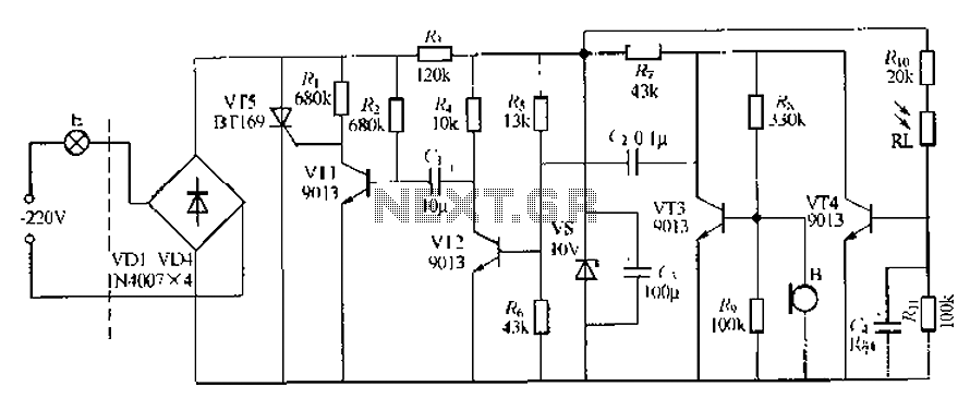
This circuit describes a sound and light control delay system for a walkway stairs light switch. It involves various components including 220V AC electric bulbs, diodes (VD1-VD4), and resistors. The circuit utilizes a rectifier regulator to stabilize the voltage...
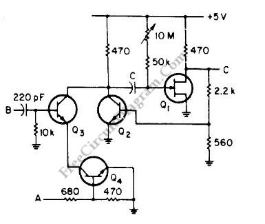
This is a versatile discrete monostable circuit. The circuit consists of a 2N3819 JFET and 2N3704 transistors. This monostable multivibrator circuit has an additional input to enable or inhibit the function at any time without causing an output pulse....
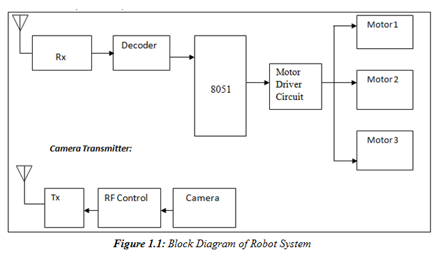
A prototype model of an agriculture-based robot has been developed to address the challenges faced by farmers who have traditionally relied on manual labor for cultivating their lands. The increasing urbanization has led to a shortage of labor, as...
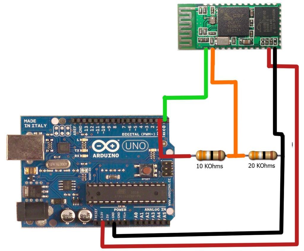
The motion games on the Nokia 5800 sparked an interest in creating a real-world version of a racing car controlled by tilting a phone. The motion-controlled robot, named Hercules due to its high torque and speed, is operated via...
This discrete voltage regulator features capabilities equivalent to modern voltage regulator integrated circuits (ICs). While constructing a discrete version may not be cost-effective, studying the schematic diagram provides valuable insights into its operation. The circuit includes a resistor of...
A robot that dances to music. It would be fascinating to have a small robot on your desk dancing to music from Fatboy Slim. Winamp provides an API for writing music visualization plug-ins. A plug-in was developed that sends...