
Discrete Sliding Tone (Frequency Ramp) Doorbell
 Doorbell")
The described doorbell circuit utilizes a combination of resistors, capacitors, and diodes to achieve a unique audio output. The AF oscillator's frequency is primarily influenced by the total resistance Rbg, which is a function of R1, R2, and R3. The initial setting of R2 plays a crucial role in determining the starting frequency of the doorbell tone, ensuring it is both audible and pleasant to the user.
The charging behavior of capacitor C3 is critical in the operation of the circuit. As C3 charges through resistor R6, it reaches a threshold voltage that activates diode D1. Once D1 conducts, it modifies the resistance seen by the oscillator, allowing for a dynamic change in frequency. The interaction between Rbg and the diodes creates a feedback mechanism that results in a frequency sweep as the capacitor charges.
The inclusion of multiple diode paths is a sophisticated design choice that enhances the performance of the circuit. By providing two conduction paths with different biasing conditions, the circuit can maintain a linear transition in frequency even as the voltage increases. This feature not only improves the tonal quality of the output but also ensures that the transition between low and high frequencies is smooth and musically pleasing.
Overall, this doorbell circuit exemplifies a thoughtful integration of electronic components to create an effective and aesthetically pleasing audio output. The careful selection of resistors, capacitors, and diodes allows for a versatile design that can be easily adjusted to meet specific user preferences.This doorbell circuit produces a low tone that will slide up to higher frequency. The equivalent total resistance connected between the base of Q1 and ground (Rbg), and coupling capacitor C1 determines the AF oscillator`s frequency. The resistance (Rbg) is equal to (R2 R1)R3. Here is the schematic diagram of the circuit: The R2 is used to set the initial bias condition, adjusted to produce a pleasant low starting frequency doorbell tone. D1 will start to conduct when Capacitor C3 charge through R6 until it reaches D1 bias voltage level. Then the value of Rbg is paralleled by R4 and D1, and R5-D2-D3, and the values of diode`s equivalent resistance is gradually decreased as the C3 voltage ramp up. This decreasing resistance value make the output tone slides up in frequency. Two different diode path is provided to extend the linear area of diode conduction transition slope. With two path with different biases, after the single diode path has saturated, the second path provide further linear increase at higher voltage level.
🔗 External reference
Related Circuits
In all the houses exist the bells in the door. All want, they have the possibility of being possible to change the intensity, the tone of sound. With this circuit we have this possibility. With the materials round the...
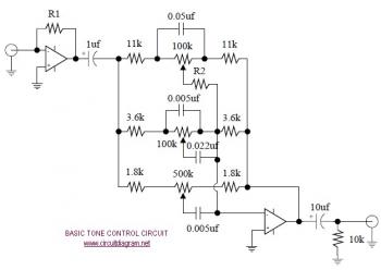
The following diagram illustrates the schematic of an Active Tone Control circuit, commonly referred to as "ACTOR." The ACTOR is an electronic audio circuit designed to enhance loudness by adjusting bass and treble audio signals. It operates using the...
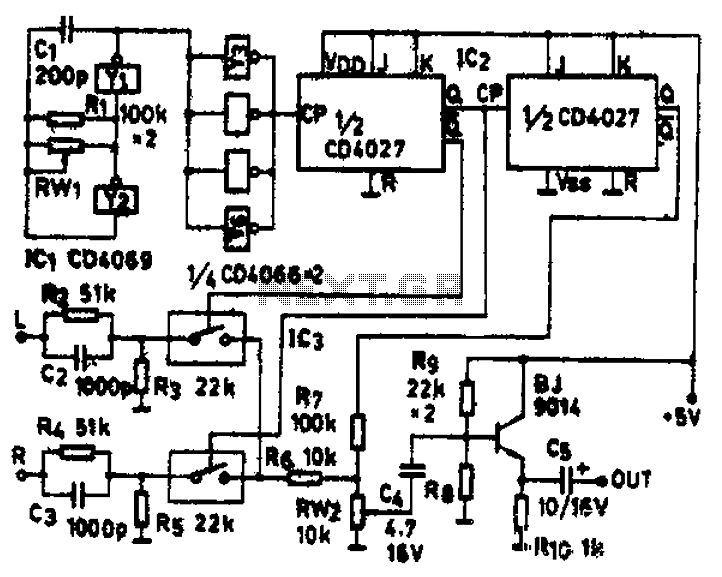
The circuit schematic diagram features IC1 (4069) and components Y1 and Y2, which together form a frequency oscillator operating at 76 kHz. Components Y3 to Y6 provide isolation and shape the output into the IC2 (CD4027) dual JK flip-flop,...
This circuit utilizes a synthesized sound chip from Holtek, the HT-2811, which produces the sound of a "ding-dong" chiming doorbell. Additionally, it incorporates a CMOS 4026 counter display driver integrated circuit (IC) to tally the number of visitors. The...
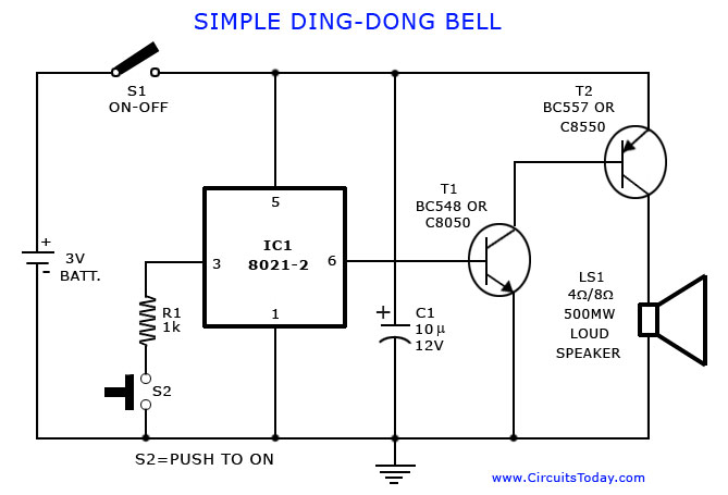
A tone generator circuit, which can be used to create a simple calling bell circuit, is illustrated here. It is constructed using the 8021 integrated circuit (IC), which includes built-in circuitry for producing a "ding-dong" sound. The tone generator circuit...
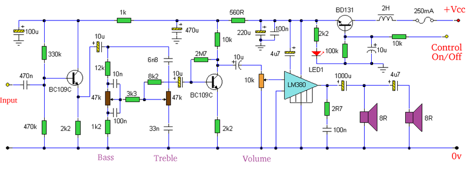
Built around an LM380, this amplifier includes tone controls and electronic soft switching. The soft switching circuitry ensures power is balanced. The LM380 is a power audio amplifier capable of delivering up to 14 watts of output power. It is...