
Display circuit

The EDE702 is a microcontroller that interfaces with various display technologies, including the HD44780-compatible LCDs. Its integration into the Secure DigitalWriter box allows for enhanced functionality, although the differences in command protocols between the EDE702 and the LED-backlit LCD character display necessitate careful consideration during design and implementation. The separation of the EDE702 onto its own board is a practical solution to manage the complex wiring required for the display, ensuring that each connection is secure and properly routed.
The single-row header used for connecting the display board simplifies the assembly process, allowing for a straightforward connection to the display. This design choice minimizes potential errors during installation and provides a clean interface for the user. The decision to operate the LED backlight at 80 mA, rather than the initially suggested 240 mA, demonstrates a thoughtful approach to power management and thermal considerations. By incorporating a heatsink on the regulator, the design mitigates the risk of overheating, ensuring reliable operation of the display.
The choice of a black on yellow display enhances visibility, particularly in indoor environments where lighting conditions can vary. The wide field of view is advantageous, as it allows multiple users to read the display from different angles without significant loss of contrast or clarity. Overall, the design considerations taken into account for the integration of the EDE702 and the LED-backlit LCD character display result in a functional and user-friendly interface suitable for various applications.Had bought this EDE702 some time ago, and a LED-backlit LCD character display. After buying the EDE702, I considered that it did not provide enough integration with HD44780-compatible displays to justify its price. Nevertheless I should use it, as it would be more use set up than lying in a box. It was convenient to put it in the Secure DigitalWriter box, as there was room for the display, and the
serial infrastructure already was in it. However, the display and the writer are not compatible, since they require different commands. Although the existing board has enough space for the EDE702, it was put on a separate board because of the large number of connections to the display. The display board plugs directly into the display with a single-row header. I was not sure how much current the LED backlight should have, since I did not have a data sheet which matched the marking on the display, and it did not have a dropping resistor.
A data sheet for a similar-appearing display gave 240 mA for the backlight, but this seemed excessive, so after experimenting I chose 80 MA, which did require rework of the writer board to put a heatsink on the regulator. This display is black on yellow, and is very readable indoors, with a good field of view. 🔗 External reference
Related Circuits
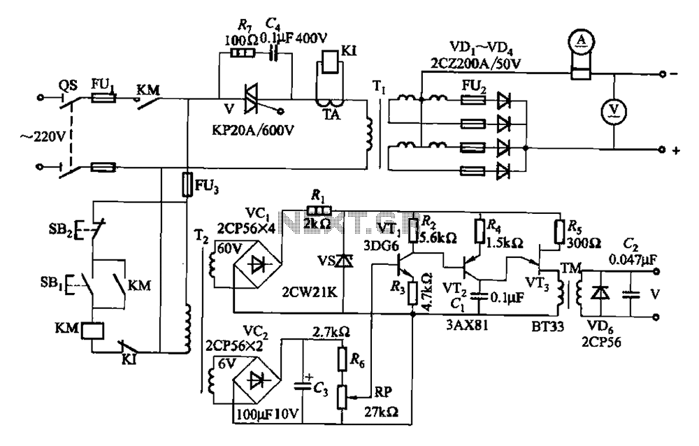
A 500A-6V single-phase power supply circuit designed for thyristor electroplating. This circuit can output a continuous DC current of 500A at 6V, which is adjustable for plating processes. It incorporates a single-junction transistor as part of the trigger circuit,...
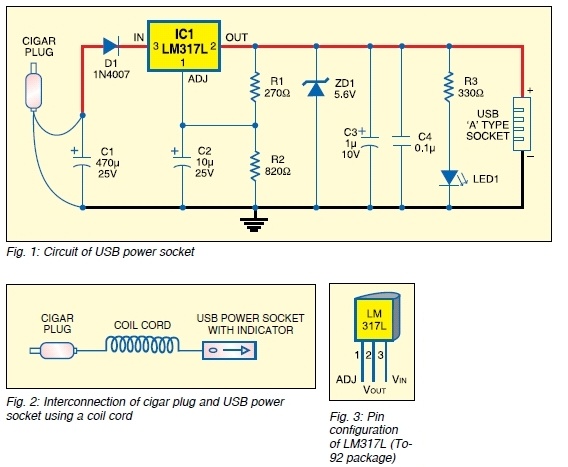
The safe 12V car adapter described here can be used to limit the current from a +12 volt car battery, available from the in-dash cigar lighter power port, to below 2.6A. The 12V car adapter is designed to ensure that...
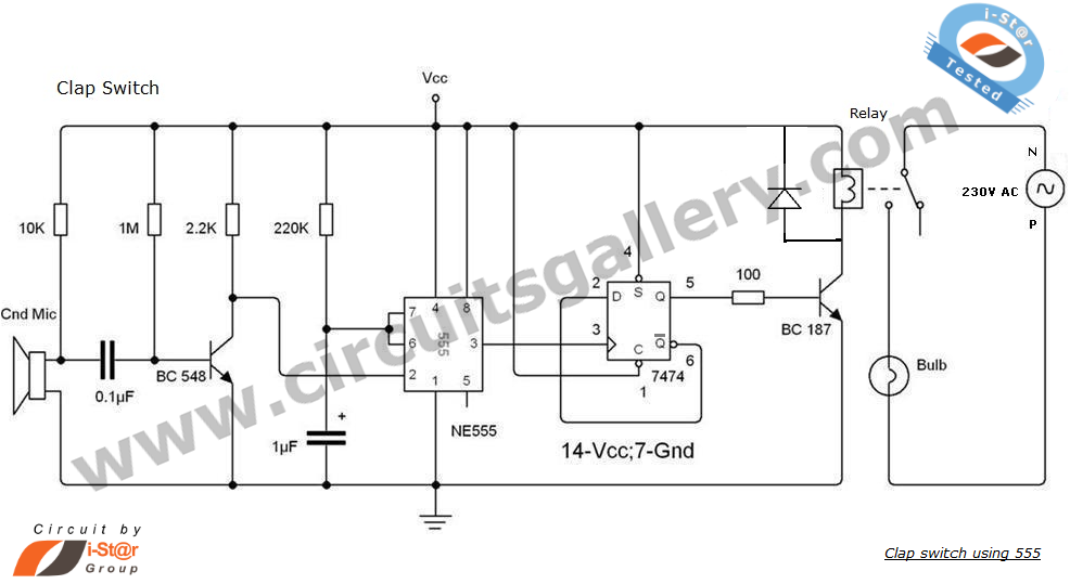
This is an intriguing 555 timer circuit designed to entertain and engage individuals while studying electronics in educational settings. Commonly referred to as a clap switch circuit, it operates as a sound-controlled flip-flop. This sound-controlled light can also function...
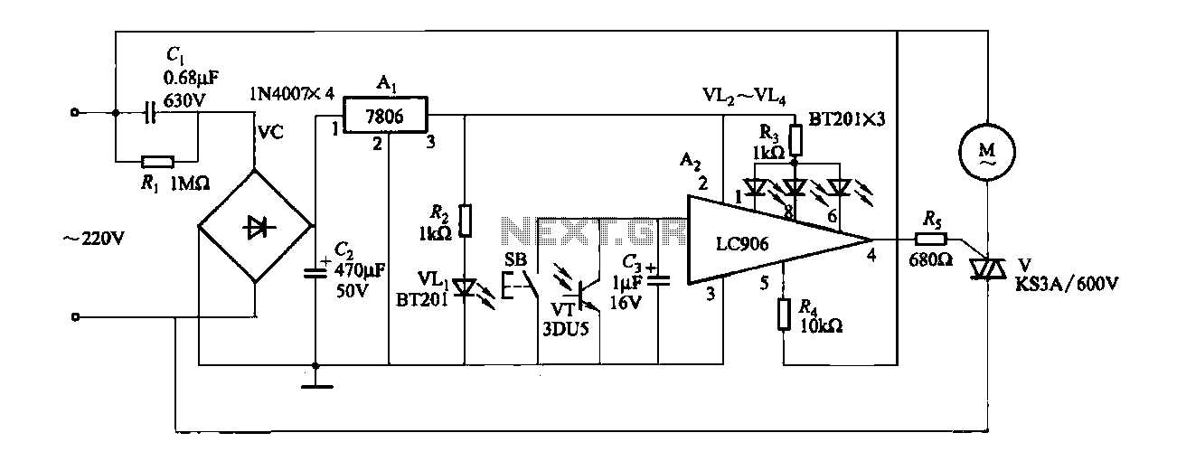
The ceiling fan speed control circuit depicted in Figure 3-6 utilizes a capacitor step-down method and a three-terminal fixed 7806 voltage regulator. It achieves fan speed control through the integrated circuit A2, which regulates the conduction angle of the...
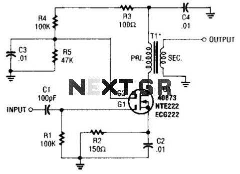
A MOSFET is utilized as a wideband buffer amplifier. T1 is wound on a toroid of approximately specified diameter, using material suitable for the frequency range, typically between 1 MHz and 20 MHz. The turns ratio should be approximately...
This circuit serves as a dependable alternative to thermally-activated switches designed for flashing Christmas tree lamps. The arrangement consisting of Q1, Q2, and associated resistors activates the silicon-controlled rectifier (SCR). The timing function is determined by resistors R1, R2,...