
Do Oscillation Building Circuit by Your Self!

An oscillator circuit is essential in various applications, including signal generation, clock pulses for digital circuits, and waveform shaping. The Flip-Flop/Bi-stable circuit is a type of digital memory circuit that can hold one of two states indefinitely until triggered to switch states. It is commonly used in memory storage and data processing applications.
The Monostable Multivibrator, on the other hand, is a circuit that generates a single output pulse in response to an input trigger. The duration of the output pulse can be controlled by adjusting the values of the resistors and capacitors in the circuit, making it useful for timing applications and pulse width modulation.
The Astable or Free Running Multivibrator is a circuit that continuously oscillates between its two unstable states, producing a square wave output. This circuit can be easily configured to generate a wide range of frequencies by varying the resistor and capacitor values, making it ideal for applications such as clock generation and tone generation in audio circuits.
Each of these circuits can be built using standard electronic components, and the article provides detailed assembly instructions, including schematic diagrams and component values, to facilitate construction and experimentation. By understanding the operational principles and characteristics of these oscillation circuits, users can gain valuable insights into electronic design and applications.oscillator is a mechanical or electronic device that works on this principles of oscillation. Oscillators are a basic building blockupon which the whole structure of electronics and computers is based. Here you can find an article about how to make an oscilation kit from a constant voltage which is applied to a simple circuit consisting of 2 transi
stors, 2 capacitors and 4 resistors. Sounds great, right Accordingly, you can just try to change the component value of theoscilation circuit type, then you have had a square wave generator for whatever frequency and mark/space ratio you wish. It describes three circuits, and allows you to experiment with them. Those threeoscilation circuitsare The Flip Flop/Bi-stable, The Monostable Multivibrator, and The Astable or Free Running MV.
You will have an assembly instruction and desription of each circuit within. 🔗 External reference
Related Circuits
The servo motor has numerous applications in various fields, including robotics, puppetry, photography, and more. These compact motors can accurately position their output shaft to any specified angle and maintain that position. Most servos have a motion range of...

Vegetable greenhouse temperature detection control circuit. The greenhouse temperature detection control circuit is primarily composed of a temperature sensor SL234M, operational amplifiers LM324 and LM358, a dual time base circuit NE555, a relay, and a display driver circuit. The...
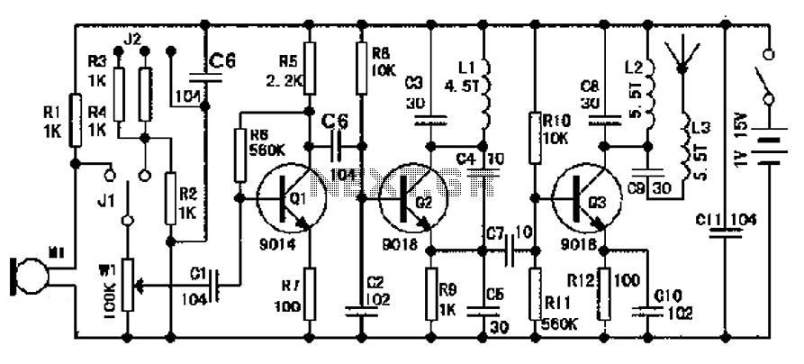
The design of an FM radio transmission frequency band enables compatibility with any FM radio receiver, allowing the high-frequency signal to be transmitted and restored from an audio signal. This technology serves various applications. Applications of a wireless microphone...

The circuit is a common three-terminal linear regulator expansion flow circuit. In practical applications, it may encounter some well-considered or lower false failures. 1. Disadvantages of this power supply: 1.1 This power supply is a linear regulator...
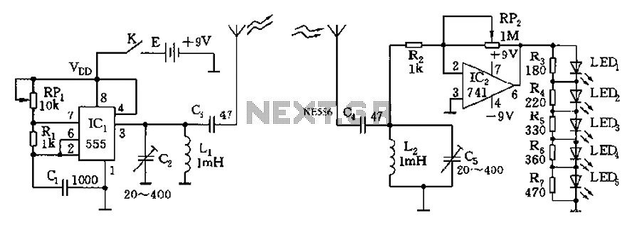
The circuit diagram of the device features a 555 timer IC configured as a transmitter and a receiver, divided into two sections. The 555 timer in the transmitter section serves as the core component of a frequency oscillator. The...
A long time ago, when telephones were simple and reliable from an electrical standpoint, telecom operators installed surge protection on all telephone lines at risk from storms. Paradoxically, as modern technology has led to the use of delicate and...