
Domestic Seismic Alarm

The seismic alarm circuit consists of several key components that work together to detect seismic activity and trigger an alarm. The core of the system is IC1, which serves as the primary detection unit. When the switch is turned on, it enables the detection mode, allowing the circuit to monitor for seismic events.
In its idle state, when no earthquake is detected, IC1's pin 3 remains low, ensuring that VT (which may represent a relay or transistor) is not activated. This state prevents any current from flowing through the alarm circuit, keeping the system in a standby mode. The magnet is positioned close to IC1, maintaining a stable state.
Upon the detection of seismic activity, the magnet's movement causes it to shift vertically. This movement alters the magnetic field around IC1, prompting pin 3 to switch to a high state. This transition activates VT, allowing current to flow through the circuit and illuminating HL, which likely serves as a visual indicator of an alarm condition.
With VT activated, additional integrated circuits IC2 and IC3 come into play. IC2 is responsible for generating an audio signal in response to the detected seismic activity. This signal is then sent to IC3, which functions as an audio amplifier. IC3 boosts the sound output from IC2, ensuring that the alarm sound produced by BL (the buzzer or speaker) is loud enough to alert individuals in the vicinity of the seismic event.
Overall, the circuit is designed to provide a reliable alarm system for detecting earthquakes, combining visual and auditory signals to ensure effective communication of the alarm condition. The integration of multiple ICs allows for efficient processing of seismic signals and amplification of the alarm sound, enhancing the system's responsiveness and reliability.When the switch is on, the seismic alarm isin detection condition. When there is no earthquake, IC1`s pin 3 outputs low level and VT is disconnected. The alarm circuit does not work. When there is an earthquake, the magnet will move vertically. When it is away from IC1, IC1`s pin 3 outputs high level and VT is connected. HL is illuminated. IC2 and IC3 begin to work. When the sound signal output by IC2 is amplified by IC3, BL will make an alarm sound. 🔗 External reference
Related Circuits
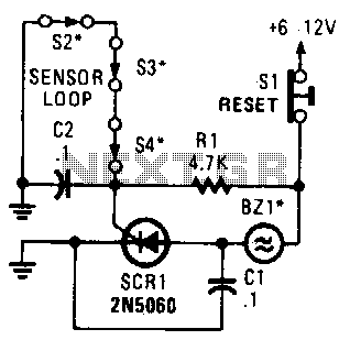
A string of three series-connected, normally closed switches is connected across the gate of a silicon-controlled rectifier (SCR). When one switch opens, the SCR is triggered through resistor R1, activating an alarm. The alarm is designed to be of...

This circuit is designed to create an early warning alarm system for any form of theft that is important to the owners of a motorcycle or bicycle. This alarm system can utilize several normally open switches, such as a...
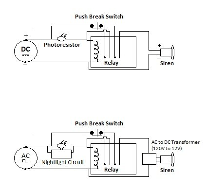
Building a DIY Alarm System: The Concept. An alarm system serves to protect property, whether it be a room, vehicle, or outdoor area. The primary function of the alarm system is to alert the designated administrator of any intrusion...
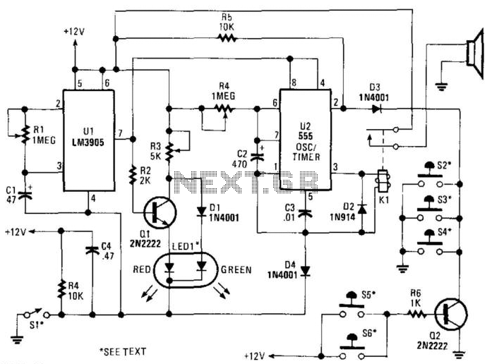
SI is an external key switch. The alarm allows a delay of 0 to 45 seconds after SI is operated before the circuit is armed. During this period, LED1 lights up green. After this delay, LED1 lights red, indicating...
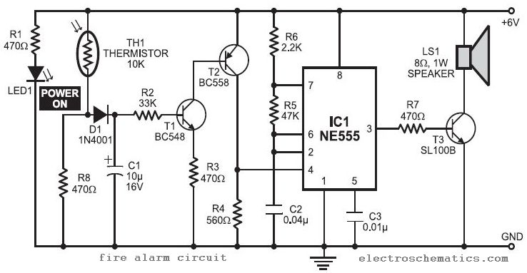
In this fire alarm circuit project, a thermistor functions as the heat sensor. When the temperature rises, its resistance decreases, and conversely, when the temperature falls, its resistance increases. Under normal conditions... In this fire alarm circuit, the thermistor is...
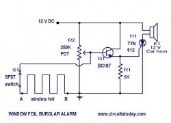
This is a simple yet effective burglar alarm circuit designed to be mounted on windows for detecting break-ins. The circuit employs a fine wire element arranged as a network within the window glass for sensing any breach. Under normal...