Downbeat-emphasized-electronic-metronome

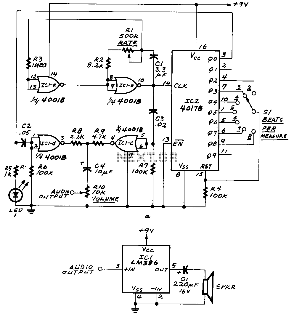
ICla and IClb form an astable multivibrator. The astable's signal is fed to IC1c, as well as to the clock input of IC2, a 4017B decade counter. The outputs Q0 through Q9 of that IC become high one at a time for each successive clock pulse received at pin 14. Switch S1 feeds one of those outputs to the reset input of the 4017B. Whenever the selected output becomes high, the 4017B restarts its counting cycle, which determines the number of beats per measure. The network composed of C2 and R6 sharpens the downbeat pulse, while the network composed of C3 and R7 sharpens the free-running pulses. By making C2 larger than C3, the downbeat receives greater emphasis.
The circuit utilizes an astable multivibrator formed by operational amplifiers ICla and IClb, generating a continuous square wave output. This signal is routed to IC1c, which serves as an intermediary stage before driving the clock input of the 4017B decade counter (IC2). The 4017B is designed to count in a sequential manner, activating its output pins Q0 through Q9 sequentially with each clock pulse received at pin 14. The functionality of the circuit is enhanced by the inclusion of switch S1, which allows for the selection of one of the decade counter's outputs to be connected to its reset input.
This reset feature is crucial, as it permits the 4017B to restart its counting cycle upon receiving a high signal from the selected output. This action effectively controls the number of beats per measure in a musical or timing application. The circuit also incorporates two RC networks, one comprising capacitor C2 and resistor R6, and the other consisting of capacitor C3 and resistor R7. These networks are designed to condition the pulse signals: the first network enhances the downbeat pulse, while the second sharpens the free-running pulses.
The design choice to make capacitor C2 larger than C3 is intentional, as it provides a more pronounced downbeat, which can be particularly beneficial in musical applications where clear rhythmic emphasis is desired. The overall configuration of this circuit allows for precise timing control and rhythmic pattern generation, making it suitable for various electronic applications that require counting and pulse generation.ICla and IClb form an astable multivibrator. The astable"s signal is fed to IC1c, also to the clock input of IC2, a 4017B decade counter. That IC"s QO through Q9 outputs become high one at a time for each successive clock pulse received at1Jin 14. Switch Sl feeds one of those outputs to the 4017B"s reset input. Whenever the selected output becomes high, the 4017B restarts its counting cycle; that determines the number of beats per measure. The network composed of C2 and R6 sharpens the ~downbeat pulse, and the network composed of C3 and R7 sharpens the free-running pulses.
By making C2 larger than C3, the downbeat receives greater emphasis.