
DTMF Remote Domestic System Control

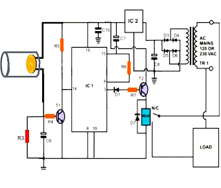
The DTMF Remote Domestic System Control Circuit is designed to enable control of domestic appliances through DTMF signals, which are typically generated by pressing keys on a telephone keypad. This circuit utilizes a radio frequency (RF) transmission method to send DTMF signals wirelessly, allowing for remote operation of devices within a specified range.
The circuit typically consists of several key components: a DTMF decoder, a microcontroller, and an RF transmitter. The DTMF decoder receives the audio signal generated from the telephone keypad and converts it into a digital signal that can be processed by the microcontroller. The microcontroller interprets the DTMF signals and determines which appliance to activate or deactivate based on the received commands.
The RF transmitter is responsible for sending the processed signals to the corresponding RF receiver, which is connected to the domestic appliances. The RF receiver decodes the incoming signals and triggers the appropriate relay or switch, thereby controlling the connected devices.
In addition to the basic functionality, the circuit may include features such as feedback indicators (LEDs) to confirm the status of the appliances, as well as safety mechanisms to prevent unintended operation. Power supply considerations are essential, and the circuit may utilize battery-operated or mains-powered options, depending on the application requirements.
Overall, this DTMF Remote Domestic System Control Circuit provides a convenient and efficient method for remotely managing household appliances, enhancing user convenience and automation in domestic environments.The following circuit shows about ?DTMF Remote Domestic System Control Circuit Diagram. Features: DTMF signals can be transmitted over a radio to . 🔗 External reference
Related Circuits
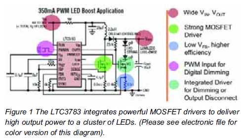
High brightness (HB) and super HB LEDs are utilized in LCD TFT backlighting for high-end televisions, industrial lighting, and projectors. A notable application is in instrument panel backlighting, interior lighting, and brake lights of various vehicles. Luxury automobile manufacturers...
An exhaust fan is a crucial component in kitchens. This document presents a simple circuit designed to control kitchen fans by monitoring the ambient temperature. It is built around... The circuit for controlling an exhaust fan based on ambient temperature...
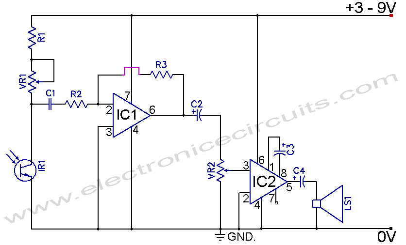
The following post illustrates a simple light-operated remote control circuit that can be activated by an ordinary flashlight or, more effectively, through a laser beam unit (keychain type). The Light Dependent Resistor (LDR) is connected between the base of...
Infrared Remote Control Tester Circuit. This is a simple circuit that can be built to test infrared remote controls. The circuit utilizes an... This infrared remote control tester circuit is designed to verify the functionality of infrared remote controls commonly...
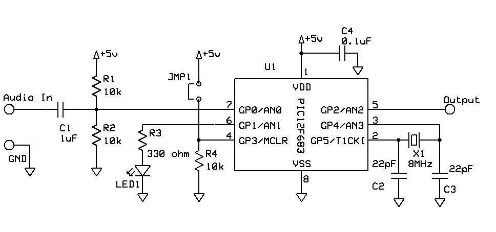
DTMF Touch Tone Decoder Using Microchip PIC Microprocessor. This project contains the details of using a Microchip PIC12F683 8-bit microprocessor to detect Dual-Tone Multi-Frequency (DTMF) signals. The DTMF Touch Tone Decoder circuit utilizes the Microchip PIC12F683 microprocessor, which is an...

This is the power diagram for motor forward and reverse operation. To change the motor direction, one polarity must be altered, for example, changing R to S. For detailed information, please refer to the following. The described power diagram illustrates...