
Dual astable multivibrator

The dual astable multivibrator is a fundamental electronic circuit that operates continuously between its high and low states, producing a square wave output. This configuration utilizes two timing resistors and capacitors, allowing for a wide range of duty cycle adjustments. The duty cycle, defined as the ratio of the time the output is high to the total period of the cycle, can be finely tuned from 5% to 95%, making this circuit highly adaptable for various applications in digital electronics.
In many digital systems, two-phase clock signals are essential for synchronizing operations between different components. The dual astable multivibrator provides two outputs that are 180 degrees out of phase, which can be utilized to drive flip-flops, counters, and other sequential logic devices. This feature enhances the circuit's utility in complex digital systems where timing and synchronization are critical.
The circuit includes reset terminals that allow for inhibition of the oscillation. By applying a signal to either reset terminal, the output can be forced to a low state, effectively halting the clock signals. This functionality is particularly useful in situations where it is necessary to pause operations or reset the timing sequence without altering the physical components of the circuit.
Overall, this dual astable multivibrator is a versatile and essential component in the design of digital systems, providing adjustable timing characteristics and dual-phase outputs that facilitate effective synchronization across various electronic applications.This dual astable multivibrator provides versatility not available with single timer circuits. The duty cycle can be adjusted from 5% to 95%. The two outputs provide two phase clock signals often required in digital systems It can also be inhibited by use of either reset terminal.
Related Circuits
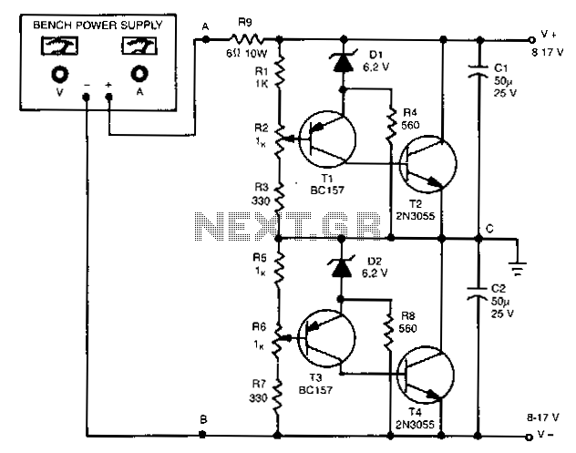
The outputs in this circuit are independently variable and can be loaded unsymmetrically. The output voltage remains constant, regardless of load and changes. By varying potentiometers R2 or R6, the output voltages can be conveniently set. Outputs can be...
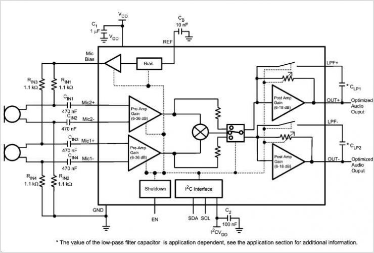
Figure 1 illustrates the schematic for a universal input, 7.6 V, 700 mA constant voltage/constant current (CV/CC) power supply designed for LED driver applications. This design employs the LinkSwitch-II product LNK606PG in a flyback configuration. The LNK606PG (U1) integrates...
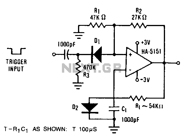
The circuit demonstrates the functionality of the HA-5151 as a battery-powered monostable multivibrator. In this configuration, the time constant is set to 0.632, simplifying the time constant equation to T = R1 * C1. Diode D2 is employed to...
Two 47k ohm resistors, with alternative values ranging from 22k to 100k ohm, can be used. The value of these resistors affects the timing of the blinking; larger values result in slower blinking. In a typical electronic circuit designed for...
Here is a circuit diagram designed for DIY enthusiasts who aim to construct a dual fan controller utilizing an ATtiny45 microcontroller. The circuit activates the first fan when the temperature reaches a user-adjustable dial setting and engages a second...
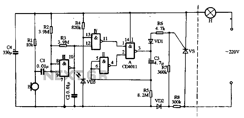
The main circuit utilizes a two-input NAND gate composed of four digital integrated circuits. This includes a NAND gate microphone amplifier circuit, a light control mechanism using an "AND gate," and a monostable delay control circuit formed by NAND...