
Dual DC motor speed control

The described circuit is an advanced DC motor speed control system utilizing an efficient PWM H-bridge configuration based on MOSFET technology. The design operates within a supply voltage range of 4.2 to 13 volts and can handle high currents up to 65 amps, making it suitable for driving large motors. It is designed to interface with standard RC hobby receivers, allowing for individual control of two motors. The system facilitates a "tank-like" driving experience by mixing steering and throttle inputs, which is particularly beneficial for robotics and remote-controlled vehicles.
At the core of the control logic is a Microchip PIC16F876 microcontroller, which receives signals from a two-channel RC receiver. The microcontroller processes these signals, generating two PWM outputs and four direction control signals. The use of four 4001 NOR gates enables the combination of PWM and direction signals, effectively driving the Analog Devices ADP3417 MOSFET high-low drivers. The ADP3417 is specifically chosen for its capability to operate at low supply voltages and includes features such as overlap protection to prevent simultaneous conduction of high and low side MOSFETs, thus enhancing reliability and efficiency.
The power MOSFETs utilized in this design are the IRF3704, selected for their high current handling capacity, low on-resistance, and low gate threshold voltage. The inclusion of an internal P-N junction diode within the MOSFETs eliminates the need for additional fly-back diodes, simplifying the circuit design.
To ensure stable operation, the design incorporates an LM2940 voltage regulator, which provides a low dropout voltage of 0.5 volts at a 1 amp load. This regulator also features reverse battery protection, short circuit current limiting, and thermal overload protection, contributing to the overall robustness of the system.
The choice of the PIC16F876 microcontroller is strategic, as it offers two PWM outputs and ample program space, facilitating easier software development. Although smaller PIC microcontrollers could have been employed, the larger model simplifies the coding process.
For practical assembly, all components were ordered in a DIP format, with the exception of the ADP3417, which was adapted to a DIP socket despite its SOIC package. This decision reflects a preference for ease of assembly over compactness, although a more space-efficient design could be achieved by utilizing smaller packages for all components. The design does not incorporate heatsinks for the MOSFETs, which is generally advisable; however, the expected current draw from the motors is low enough to mitigate overheating concerns.Here is a design for a DC motor speed control featuring: Efficient PWM H-bridge MOSFET architecture. Supply (battery) voltage range from 4.2 to 13 volts. High current capacity for driving large motors (65 amps max). Input compatible with standard RC hobby receivers. Individual control of 2 motors. Mixing of steering and throttle into "tank like" drive control. BEC (battery eliminator circuit). Proportional forward and reverse on both motors. A Microchip PIC16F876 interfaces to a standard 2 channel RC receiver. The PIC device mixes the 2 channels together, and generates 2 PWM signals, and 4 direction signals. 4 4001 NOR gates combine the direction and PWM signals to drive Analog Devices ADP3417 MOSFET hi-lo drivers. The IRF3704 power MOSFET device was chosen for it's large current capacity, low on resistance, and low gate threshold voltage. This device also has a large built in reverse P-N junction diode capable of large currents, thus eliminating the need for external fly-back diodes.
The ADP3417 MOSFET driver was ideal for this application. It operates with very low supply voltages, includes overlap protection (to make sure both hi and lo devices are never on at the same time), performs the bootstrap operation for the hi MOSFET, and uses very little supply current. The LM2940 regulator was chosen for it's low dropout voltage (0.5v at 1.0amp load) features reverse battery protection, has a short circuit current limit, and also has thermal overload protection.
Finally the PIC16F876 was chosen for it's 2 PWM outputs and large program space. This made the software easy to implement. A smaller PIC could have been used, but would make software development harder. To ease my job building the circuit board, I ordered all of the parts in a large DIP format. I even ordered a large format crystal. The ADP3417 was only available in a small SOIC package, but I soldered it onto a DIP socket anyway. A much smaller circuit board could be built by using smaller SOIC packages for all of the components. The MOSFET devices are not heatsinked. This is a bad idea, but the DC motors I am using don't draw much current (maybe 5 amps max, 0.5 amps typ), so the MOSFETs don't get hot.
🔗 External reference
Related Circuits
Camping today often requires bringing various electronic devices for daily activities or entertainment. Frequently, a charge is needed for these devices. In modern camping scenarios, the reliance on electronic devices has significantly increased. Campers typically bring smartphones, tablets, GPS devices,...
Described here is a very inexpensive solution to many phono-controlled applications like remote switching on, for instance, or activating a camera, tape recorder, burglar alarms, toys, etc. The circuit given here employs a condenser microphone as the pick-up. A...

To create a PWM controller, begin with a sawtooth generator powered by a 7.5V regulated supply to achieve a Vpp of 5V. Connect the sawtooth output to one input of a comparator and the MAP voltage to the other...
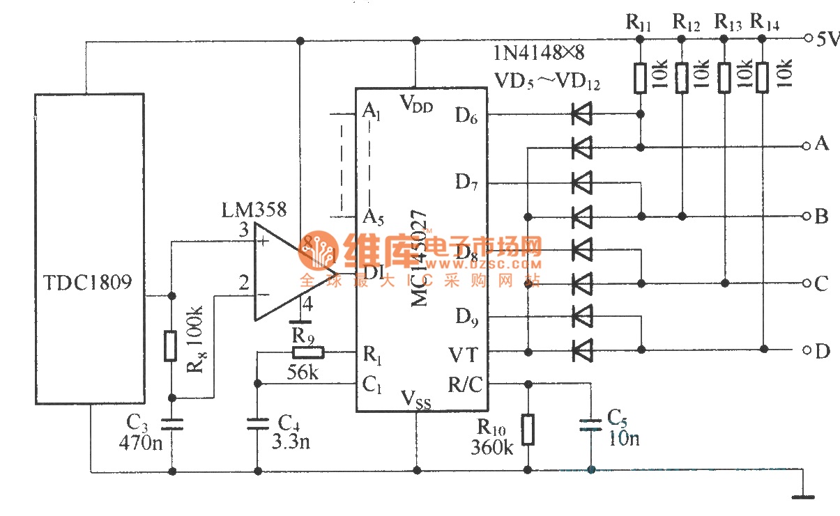
The TDC1808/TDC1809 is a pair of wireless remote control transmitter and receiver components. They utilize an internal antenna to transmit both digital and analog signals. These components are suitable for various wireless remote control devices. Key features include compact...
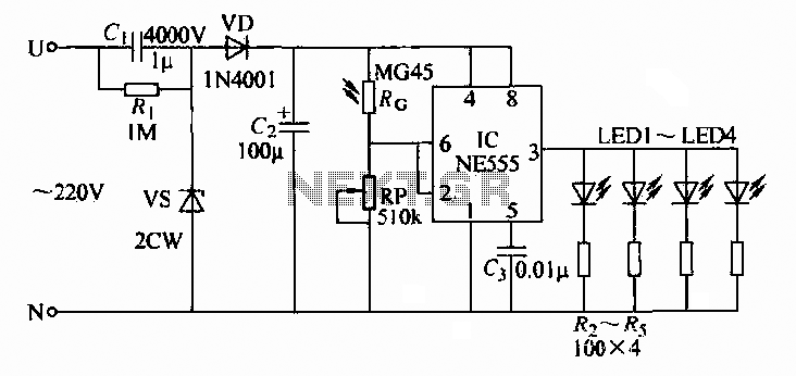
A 220V AC input is converted to a DC operating voltage of approximately 3.3V using a capacitive G buck regulator, a rectifier diode (VD), and a filter capacitor connected to an NE555 integrated circuit (IC). The IC functions as...
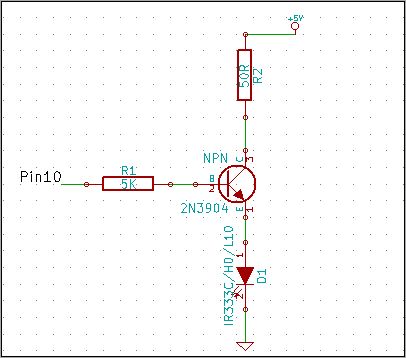
The 2N3904 is an NPN transistor. When observing the flat face of the transistor, the left lead is the Emitter (pin 1 in the schematic), the middle lead is the Base (pin 2 in the schematic), and the right...