
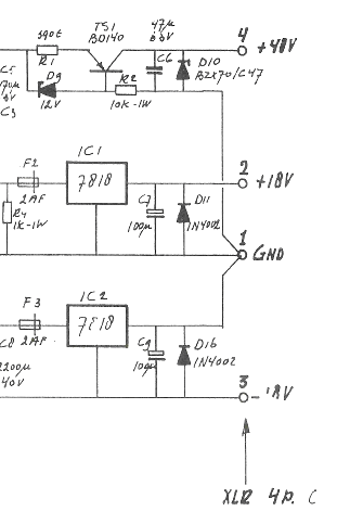
Dual Voltage 12V Power Supply

The dual voltage power supply circuit is designed to provide both positive and negative regulated outputs, making it suitable for various applications that require dual polarity power. The circuit utilizes two linear voltage regulators, the AN7812 and AN7912, which are capable of delivering stable output voltages of +12V and -12V, respectively.
The power supply begins with a step-down transformer that converts the high voltage AC input (ranging from 110V AC to 220V AC) to a lower AC voltage, typically between 12V AC to 24V AC. This transformer should be rated for at least 500mA to ensure sufficient current delivery to the load. The secondary winding of the transformer feeds into a bridge rectifier, which converts the AC voltage to a pulsating DC voltage.
Following the rectification, the output is smoothed using capacitors. A large filter capacitor is placed across the output of the rectifier to reduce voltage ripple, ensuring that the voltage supplied to the regulators is as stable as possible. The AN7812 regulator takes the positive side of the rectified output, while the AN7912 handles the negative side. Each regulator requires bypass capacitors at their input and output terminals to enhance stability and transient response.
Typically, a 0.33µF capacitor is connected at the input of each regulator, and a 0.1µF capacitor at the output. These capacitors help filter high-frequency noise and improve the overall performance of the power supply.
The output terminals of the regulators provide the required +12V and -12V, which can be used to power various electronic circuits and devices that operate within this voltage range. This dual voltage power supply is particularly useful in applications such as operational amplifier circuits, analog signal processing, and other electronics requiring dual rail power. Proper heat sinking may be necessary for the voltage regulators to dissipate heat generated during operation, ensuring reliable performance and longevity of the components.The following circuit Diagram of (DUAL VOLTAGE POWER SUPPLY ) can be used for Misc.. application. It requires a few components to built. The most important components of this circuit are REGULATORS. 1 : (AN) 7812 and 2 : (AN) 7912 AN7812 is the Positive Voltage Regulator. It regulates the voltage from (almost) 24vDC to 12vDC (accurate). AN7912 is the Negative Voltage Regulator. It regulates the voltage from (almost) -24vDC to -12vDC. A transformer output must be between 12vAC to 24vAC @ 500mA. Input of transformer (Primary) should be about 110vAc-220vAC. It also include some capacitors to filter the current. 🔗 External reference
Related Circuits
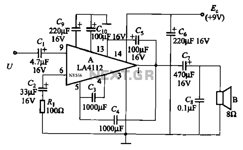
Audio power amplifier circuit utilizing the LA4112 integrated power amplifier along with additional components as shown in the figure. The audio power amplifier circuit based on the LA4112 integrated power amplifier is designed to deliver high-quality audio amplification for various...
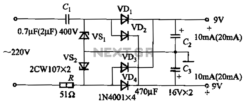
The circuit's output current capacity is influenced by the bulk capacitor Cl. When the capacitance of Cl is changed from 0.7 µF to 2 pF, the output current can be increased from approximately 10 mA to around 20 mA,...
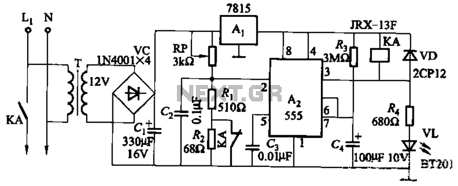
This circuit is applicable in refrigerators and other protective devices. It employs a 7815 three-terminal voltage regulator integrated circuit and an NE555 timer IC configured as a one-shot circuit for delay control. When the voltage drops below 180V, relay...
A mixer has been purchased without a power supply unit (PSU). The user does not require the 48V phantom power and is inquiring if an 18V DC wall adapter can be used instead. Additionally, the user seeks information on...
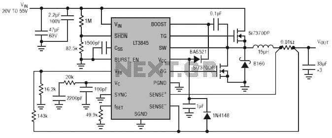
Burst Mode operation maintains high efficiency at light loads by reducing IC quiescent current to 120 µA. Light load efficiency is also improved with the reverse inductor current inhibit function, which supports discontinuous operation. Additional features include an adjustable...
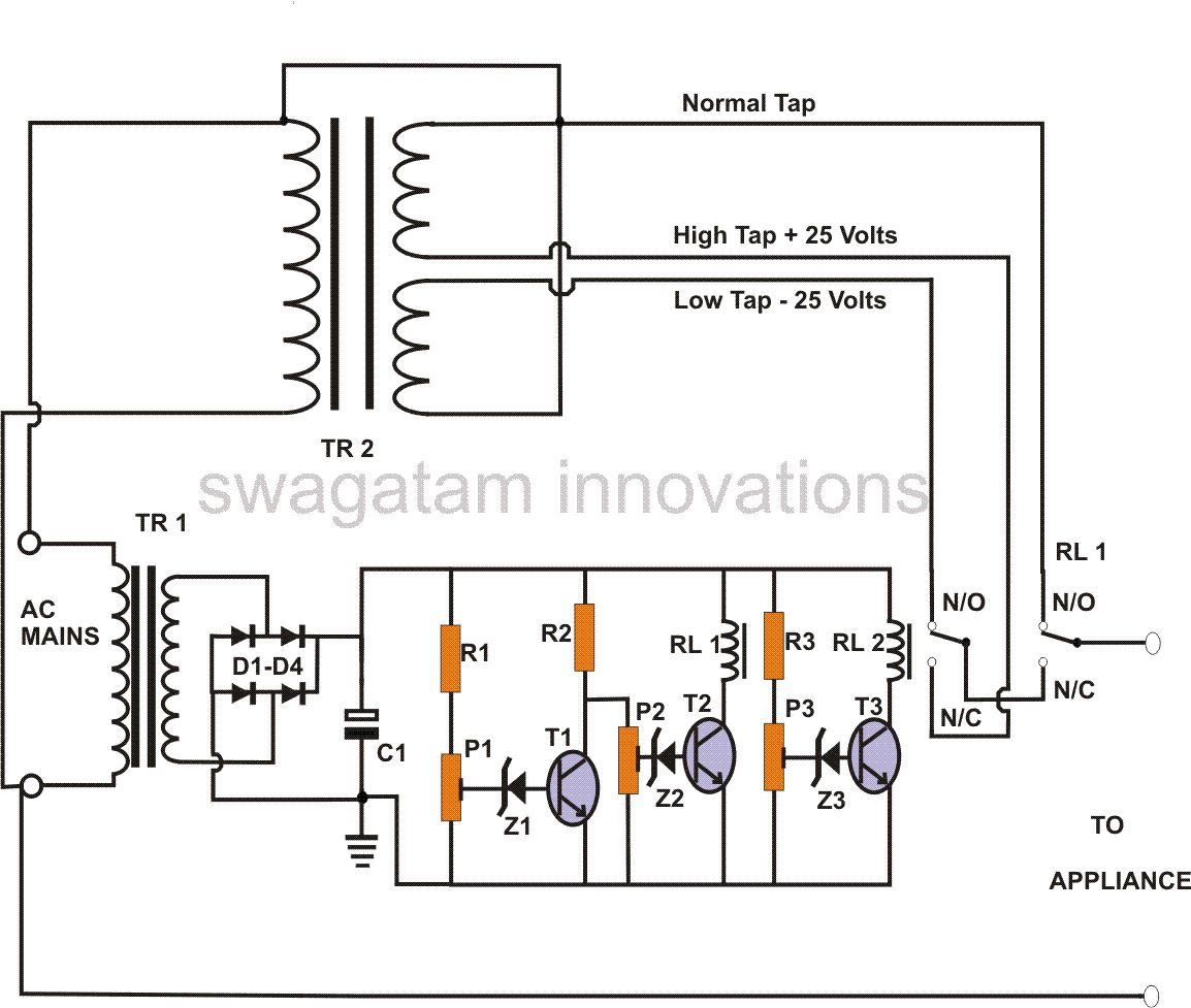
This power stabilizer circuit utilizes one relay to select either the high or low tap from the stabilizer transformer at a specific voltage level. The second relay maintains the normal mains voltage, but when a voltage fluctuation occurs, it...