
dual voltage power supply 12 volt

The dual voltage power supply circuit is designed to provide both positive and negative regulated output voltages, specifically 12 Volts DC. This is achieved through the use of two voltage regulator integrated circuits (ICs): the 7812 for positive voltage regulation and the 7912 for negative voltage regulation. The circuit typically takes an AC input from a transformer, which can handle a range of 110 to 220 Volts AC, and steps it down to a lower AC voltage in the range of 12 to 24 Volts AC.
The transformer plays a critical role in this circuit by converting high-voltage AC into a lower voltage suitable for the regulators. The output from the transformer must be rated to supply sufficient current, with a minimum requirement of 500 mA to ensure adequate power for various applications.
To smooth out the output voltage and reduce voltage ripple, capacitors are incorporated into the design. These capacitors act as filters, absorbing fluctuations in voltage and providing a more stable DC output. The use of filter capacitors is essential for maintaining the performance of the power supply, especially in sensitive electronic applications where voltage stability is crucial.
In summary, this dual voltage power supply circuit is a versatile solution for powering various electronic devices that require both positive and negative voltage rails. It is relatively simple to construct and can be adapted for different applications by modifying component values and specifications as needed.Circuit » Home » 7809 » 7812 » 7909 » 7912 » Dual Voltage » Hobby Electronics » Hobby electronics projects » RC filters » REGULATOR » transformer » Dual Voltage Power Supply 12 Volt This is the simple circuit diagram of Dual Voltage Power Supply. It is used for Misc application. This circuit is called regulated power supply. For thi s reason the main component of this circuit is Regulator IC. It also needs few components to built. The regulator 7812 is the positive voltage regulator and 7912 is the negative voltage regulator. It regulates voltage from 24Volt to 12 Volt (DC). The transformer input is 110Volt to 220Volt (AC) and the output must be between 12Volt to 24Volt (AC) and current must be 500mA. In this circuit some capacitors are used as a filter for removing repole. 🔗 External reference
Related Circuits
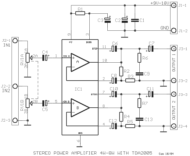
This circuit is a class AB stereo audio power amplifier designed by Quasar for high-fidelity applications using a TDA2005 module. It is straightforward to construct and requires a minimal number of external components. The module includes output current protection...
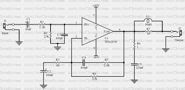
This simple 10 watts audio power amplifier is designed for home-brewed purpose. It is based on an Audio Power Amplifier IC that is called TDA2030. It is a monolithic integrated circuit in Pentawatt package, intended for use as a...
The incoming AC is routed to the primary terminals of a 12.6-volt transformer. The hot side of the AC is connected through a fuse and a single-pole single-throw (SPST) toggle switch. When the switch is in the OFF position,...
Currently, the switching power supply boasts high performance with an efficiency of 75%. The efficiency of single-scale integration switching power supplies has exceeded 90%. This advancement addresses energy concerns and enhances the performance of numerous energy-saving electrical devices. The...
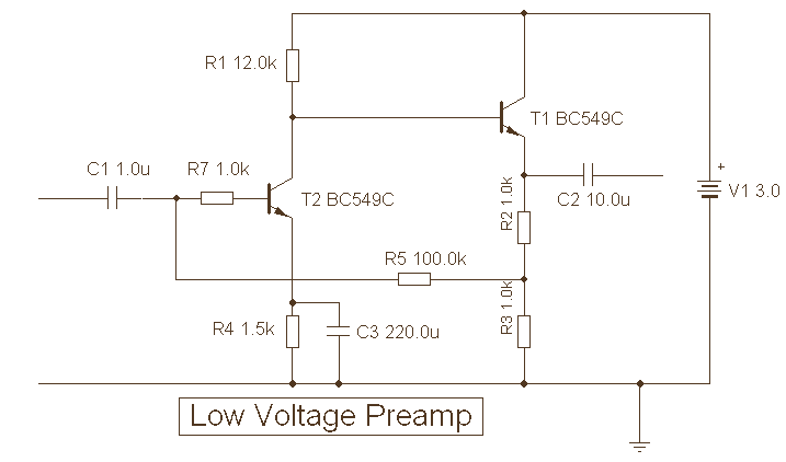
The provided description pertains to a unique low voltage variant of an audio preamp. The emitter voltage of T1 is biased close to half the supply voltage, which is 1.5V. This biasing allows for the maximum output voltage swing. The...
Many applications do not require the precision of a digital or analog (bar graph) indicator but still benefit from more than a simple low/high signal. An example is a battery charge level indicator in a car. This basic circuit,...