
E46 (BMW 3 series) Bi Xenon Wiring
The schematic for wiring E46 bi-xenon projectors is designed to facilitate the correct operation of the solenoid mechanism while minimizing the risk of damage due to high current draw. The wiring setup involves a relay system where the strong ground is activated momentarily to allow the solenoid to engage quickly. This is critical to ensure that the solenoid operates efficiently without overheating or burning out. The relay acts as a switch that can control the flow of current to the solenoid based on the input from the vehicle's lighting system.
The relay's prongs are designated in a specific manner, with the common pin typically connected to the power source and the normally open (NO) pin connected to the solenoid. The weak ground is connected to the relay's ground pin, which allows for a safe transition of power. The capacitor mentioned is used to smooth out the voltage fluctuations and provide a buffer that allows for the solenoid to operate smoothly. This capacitor's value has been chosen based on the specific requirements of the solenoid's operation, ensuring that it can handle the necessary current without causing delays or disruptions in functionality.
When modifying the ballast, it is crucial to ensure that proper sealing techniques are employed to prevent moisture ingress, which could lead to electrical failures. The removal of the plastic top should be approached with caution, and it is advisable to use heat-shrink tubing or silicone sealants around the plug connections to maintain a waterproof barrier. The overall design of this wiring schematic allows for a reliable and efficient operation of the E46 bi-xenon projectors, catering to the specific needs of different E46 models while providing flexibility in terms of relay choice and component configuration.Since a lot of people have e46 bi xenon projectors and wanna know how to wire them up correctly, without burning out the solenoid only using 2 of the 3 wires. Different e46 have different colors. I have 3 e46`s and one set has brown as a weak ground, purple with black as a strong ground, and purple as positive.
the other one I have has pink wires. the diagram refers to green as weak ground, black as a strong ground and red as positive. if you have different colors you should make sure you know which is your strong ground and weak ground as the strong one pulls 2 amps and the weak one pulls. 2 amps. The purpose of this schematic is to open the shield with the strong ground momentarily then release the strong ground and let the weak one take over.
it allows the shield to open quickly without pulling a strong current which leads to damaging the solenoid. The numbers in the diagram refer to the prongs of a relay. I forgot to mention that. You can use any automotive 4 or 5 prong relay. if you use a 5 prong relay ignore pin 87a. I would recommend bosch 30A relay from partsexpress: Because of their solid build but any relay should suffice I used a 100v 1000uF capacitor, and it takes 30 seconds + for me to be able to flash again.
i. e. flash or turn it on once and return it to low beams and I can`t return to high beams at all for 30 seconds. Did you all know you could take the plastic top off the ballasts I sure didn`t until recently. it makes them alot smaller, but you have to deal with air/moisture sealing around the plug. I did it because my engine bay is so small, but others might like not having to worry about moisture/venting problems if they have the room.
ok, added good info on the cap value, so I`m gonna put in a shameless OT plug for my new retro since the people I respect for doing such good work on these schematics are listening any advice/opinions appreciated! 🔗 External reference
Related Circuits
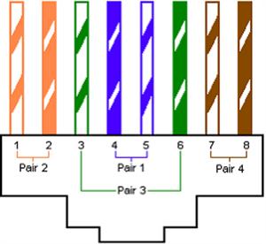
PDS addresses the limitations of standardized measures to achieve uniform materials, designs, routing, installation, and construction, creating a clear structure that is easy to manage and maintain centrally. In modern buildings, cabling has become a trend and is considered...
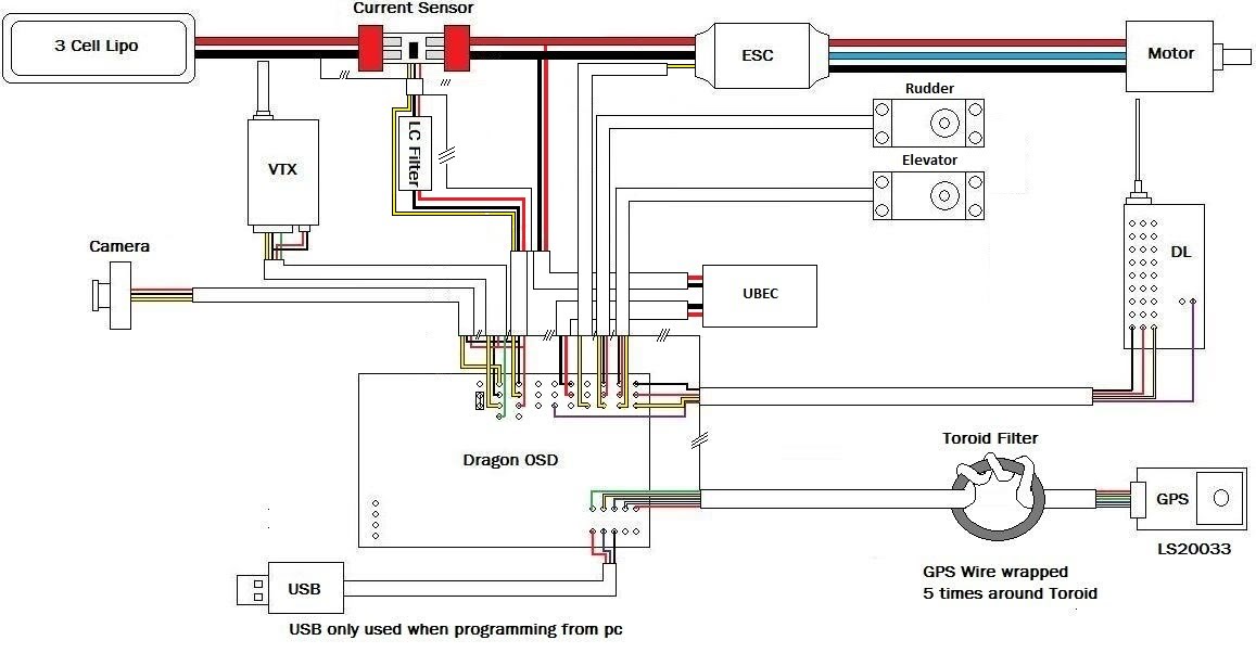
A discussion has been initiated regarding the diagrams being created. The initial set pertains to the DOSD (Dual OSD). Following the discovery of a potential issue, these new diagrams will facilitate safe wiring of the DOSD, thereby avoiding the...
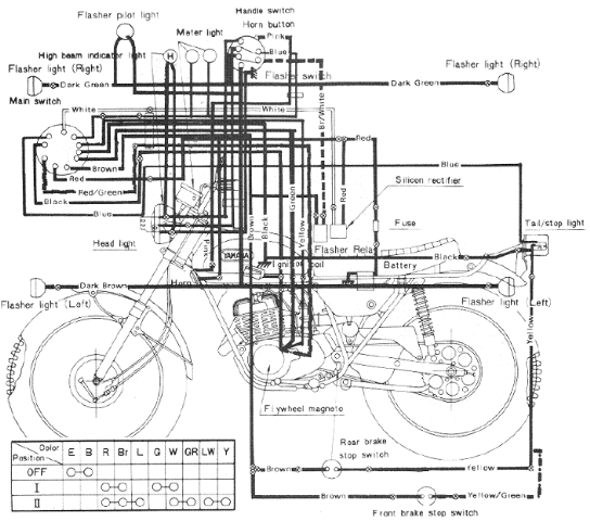
The following image illustrates the Yamaha 175 Wiring Diagram (CT2 and CT3 model) and Electrical System Schematic. It provides detailed information regarding the interconnection and wiring between electrical components of the motorcycle, including the battery, ground, headlight, taillight, horn,...
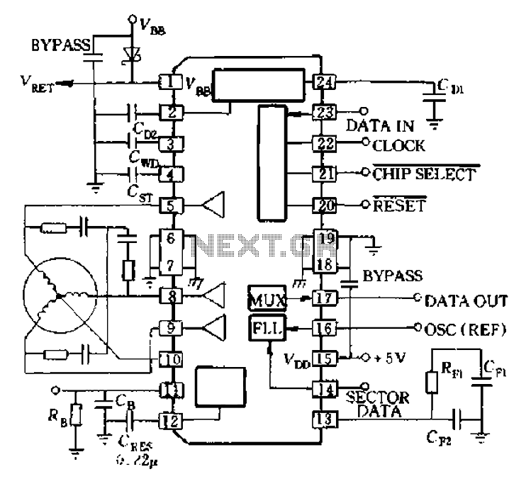
A8902 is a typical application wiring diagram. After a system failure signal from the delay island and CB 11 feeds into the motor brake, the system stops functioning until the RESET signal arrives, at which point the motor restarts. The...
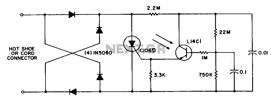
This circuit is utilized for remote photographic flash units that synchronize with the flash attached to the camera. It is designed to connect to the trigger cord or hot shoe of a commercial portable flash unit, allowing the unit...
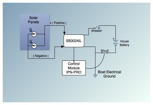
This is the fifth post in a five-part series on saving between $5,000 and $9,000 by installing a cockpit arch and a pair of solar panels on an Allied Princess ketch rigged sailboat named Aletheia. The series will continue...