
eeprom
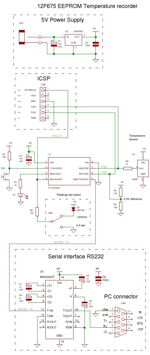
This project employs the LM35DZ temperature sensor, which outputs an analog voltage proportional to the temperature in degrees Celsius. The output of the LM35DZ is fed into the analog-to-digital converter (ADC) of the PIC microcontroller, specifically the 12F675. The ADC converts the analog voltage into a digital value that can be processed by the microcontroller. The microcontroller then stores this digital value in its internal EEPROM, which is non-volatile memory, ensuring data retention even during power outages.
The circuit includes an LED that serves as a visual indicator of the system's operation. This LED is controlled by a GPIO pin of the PIC microcontroller, which is programmed to turn the LED on after 64 readings have been stored, signaling that the storage capacity has been reached. Additionally, the circuit design includes a button for initiating the EEPROM erase sequence, allowing for fresh data logging.
For power management, the project operates at a relatively higher current draw, making it less suitable for battery-powered applications unless the LED is omitted. If battery operation is desired, using a rechargeable PP3 battery is recommended. The choice of the 12F675 microcontroller is noted as a limitation for low-power applications, and the 16F88 is suggested for applications requiring lower power consumption.
The implementation of the diode D2 is crucial during the development phase to prevent any potential voltage conflicts that could arise during programming. Once the microcontroller is programmed and removed from the development environment, the diode and resistor can be omitted if the circuit is intended for standalone operation.
Overall, this project serves as a practical demonstration of temperature data logging using a PIC microcontroller, providing a foundational understanding of interfacing sensors, data storage, and basic circuit design principles.This PIC microcontroller EEPROM project saves the temperature from an LM35DZ IC to the PIC`s internal long term data storage area. The project follows on from the last project using the virtually the same hardware. It stores temperature readings internally at regular intervals until full and after this it turns on the LED.
The LED is really just f or showing that something is happening and in a real data logger you would not use it. Note: This project is not optimized for power consumption so the best way to use it is powered from a power block. The current consumed is about 13mA (LED off) 16mA (LED on at end). If you want to use a battery use a rechargeable PP3 and do not attach the LED. The 12F675 may not the best PIC microcontroller to use for low power data logging and a better choice would be the 16F88 as it can change its internal oscillator on the fly going into slow (current saving) mode.
But you could use the 12F675 with a slow external 32kHz crystal. At every ADC reading the LED is flashed briefly and when you select a 500ms reading interval you can see the readings being taken. When 64 readings are accumulated the LED is lit permanently - showing that the data store is full. Note: For this chip you only get to store 64 results as you need to store an unsigned integer for every ADC result and this takes 2 bytes so 128 Bytes/2 = 64 results.
The solderless breadboard and circuit diagram are nearly the same as used in the previous project so if you have already built it you don`t need to do any more. Just add the blue wire, D2 and R6. At start up the led is flashed three times. If you hold the button at start up the LED is flashed six times and the internal EEPROM will be erased ready to start logging the temperature again.
As mentioned before setting GP3 high causes the measurement interval to be approximately 30 minutes whereas holding it low causes a half second measurement interval (for debug). Note the diode D2 is to stop programming voltage conflict during development. If you just program the 12F785 and then put it permanently in a separate circuit with no ICSP connection then D2 and R6 are not required - so you could connect pin 4 to 5V for half hour readings.
The software continuously gathers temperature readings and as before it transmits the result to the serial port (this time as a centigrade reading) and it also stores the reading in the EEPROM. It cangather a maximum of 64 readings (half the size of the internal EEPROM). After this it stops recording and even if the power is lost the readings will remain stored in the EEPROM.
🔗 External reference
Related Circuits
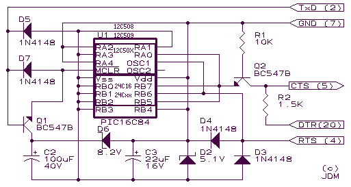
This is a JENS MADSEN project I've built to program my PIC and EEPROM (16xXXX AND 12CXXX AND 24CXX). I use it with IC-Prog; it is little, simple to build, cheap, and gives few bugs. More: When I built...
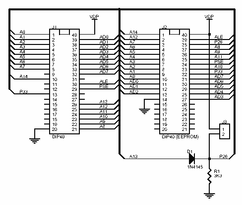
The EEprom programmer software supports the following devices 28C16 28C256 28C17 29C256 28C64. Diode D1 and resistor R1 provide the VDD isolation when programming the 24 pin devices. The jumper J3 must be shorted for 24 pin devices, and...
This is an outdated version; refer to the latest version on the documentation wiki. If you have one of Hack a Day's Bus Pirates, what should you do with it? Explore 1-Wire, I2C, and SPI EEPROMs using the 3EEPROM...
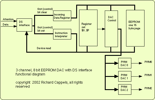
This device provides three channels of 8 bit pulse-width modulation. Output pulse duty cycle ranges from 0 to 255/256 in 255 steps. DACs may be loaded by the DS interface. DAC values may also be copied into the on-chip...
.jpg)
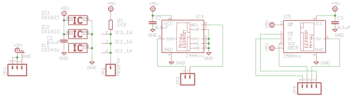
Many designers today are implementing embedded systems that require low-cost non-volatile memory. Microchip has addressed this need with a full line of serial EEPROMs, in a variety of memory configurations, using the industry-standard 2- or 3-wire communication protocols. The...
EEPROM (Electrically Erasable Programmable Read-Only Memory) is non-volatile memory, meaning it retains data even after power is removed. The ATmega168 microcontroller includes 512 bytes of EEPROM, which can be utilized to store system parameters and small amounts of data....