
Eight-channel-voltage-display
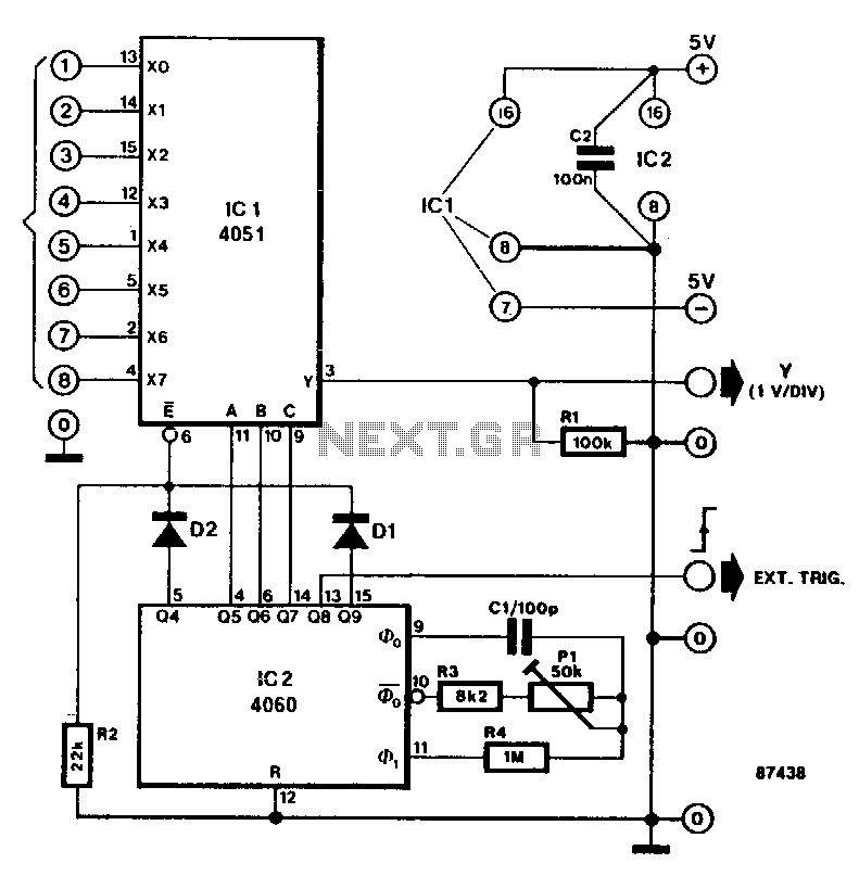
This circuit transforms a standard oscilloscope into a multifunctional eight-channel display for direct voltage measurements. The trends of each of the eight input levels can be easily monitored, although the achievable resolution is limited. The circuit diagram features an eight-channel analog multiplexer (IC1), which functions similarly to an eight-way rotary switch with contacts X0 through X7 and a common pole Y. The desired channel is selected by applying a binary code to the A-B-C inputs. For instance, the binary code 011 (A-B-C) activates channel 6 (X6Y). The A-B-C inputs of IC1 are controlled by three consecutive outputs from a binary counter (IC2), which operates at approximately 50 kHz with the assistance of a capacitor (C1). As the counter is not reset, the binary outputs Q5, Q6, and Q7 cycle through states 0 to 7. Consequently, each of the direct voltages at input terminals 1 to 8 is briefly connected to the Y input of the oscilloscope. All eight input levels can be observed simultaneously by adjusting the oscilloscope's timebase according to the duration it takes the counter to transition through outputs 0 to 7. The timebase should be set to 0.5 ms/div, with triggering configured to occur on the positive edge of the external signal. The vertical sensitivity should be adjusted to 1 V/div. The circuit's input range spans from -4 V to +4 V, with connected channels having a termination resistance of approximately 100 kΩ.
This circuit employs an eight-channel analog multiplexer (IC1), which allows for the sequential selection of input channels based on a binary code. The binary counter (IC2) generates the necessary control signals for the multiplexer, enabling the oscilloscope to visualize multiple voltage levels in a single display. The use of a binary counter ensures that the selection of channels is systematic and repeatable, providing a clear representation of input voltages over time.
The integration of a capacitor (C1) in the circuit is crucial for stabilizing the oscillation frequency of the binary counter. This frequency determines how quickly the oscilloscope can switch between input channels, impacting the overall responsiveness of the display. The specified 50 kHz frequency allows for a sufficient sampling rate to observe voltage trends without significant lag.
When configuring the oscilloscope, the timebase setting of 0.5 ms/div is essential for capturing the complete cycle of the binary counter's outputs. This setting ensures that each state transition is displayed clearly, allowing for accurate observation of the voltage levels across all channels. The vertical sensitivity setting of 1 V/div further enhances the visibility of the input signals, accommodating the specified input range of -4 V to +4 V.
The termination resistance of approximately 100 kΩ for the connected channels is designed to minimize signal reflection and maintain signal integrity, ensuring accurate voltage readings. This design consideration is particularly important in applications where precision is critical, as it helps to reduce noise and improve the overall performance of the measurement system.
In summary, this circuit effectively converts a standard oscilloscope into a versatile eight-channel display, enabling the monitoring of multiple voltage levels with reasonable accuracy and clarity. The careful selection of components and configuration settings ensures that the system operates efficiently, providing valuable insights into voltage trends over time.This circuit turns a common oscilloscope into a versatile eight-channel display for direct voltages. The trend of each of the eight input levels is readily observed, albeit that the attainable resolution is not very high. The circuit diagram shows the use of an eight-channel analog multiplexer IC1, which is the electronic version of an eight-way rotary switch with contacts XO through X7 and pole Y.
The relevant channel is selected by applying a binary code to the A-B-C inputs. For example, binary code 011 (A-B-C) enables channel 7 ( X6 Y ). The A-B-C inputs of IC1 are driven from three successive outputs of binary counter IC2, which is set to oscillate at about 50 kHz with the aid of Pl. Since the counter is not reset, the binary state of outputs Q5, Q6, and Q7 steps from 0 to 7 in a cyclic manner.
Each of the direct voltages at input terminals 1 to 8 is therefore briefly connected to theY input of the oscilloscope. All eight input levels can be seen simultaneously by setting the timebase of the scope, in accordance with the time it takes the counter to output states 0 through 7, on outputs Q5, Q6, and Q7.
The time base on the scope should be set to 0.5 ms/div, and triggering should occur on the positive edge of the external signal. Set the vertical sensitivity to 1 V /div. The input range of this circuit is from -4 V to +4 V; connected channels are terminated in about 100 KO.
🔗 External reference